H1 hxx, F t1 t13, Fault history – R&M Materials Handling VARIABLE SPEED CONTROLS ControlMaster Plus Service Manual User Manual
Page 55: 57 thermistor, Operation days
R&M Materials Handling, Inc.
4501 Gateway Boulevard
Springfield, Ohio 45502
P.: (937) 328-5100
FAX: (937) 325-5319
55/83
R&M Materials Handling, Inc. reserves the right to alter or amend the above information without notice.
The drive includes an automatic fault reset operation; the fault code stays on the display until the fault is removed
and the controller released back to 0-position. Some of the fault codes require to switch the power off before run is
possible.
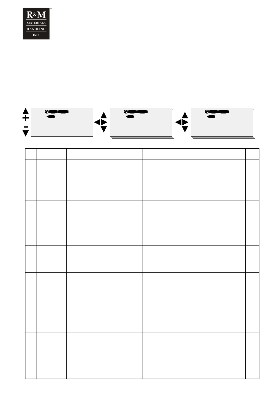
The faults are stored to the fault history, from there they can be seen if necessary. The fault history can store last
30 fault codes. Following exceptions exist when storing faults to the fault history
not stored faults: F6, F70
repeated faults are stored only once: F50, F51, F55, F60, F66, F71, F72
READY
STOP
M8.
Fault History
H1 Hxx
READY
STOP
H8.1.
57 Thermistor
F T1 T13
READY
STOP
Operation days
0
I/O term
I/O term
I/O term
T8.1.1.
Fault
code
Fault
Possible cause
Checking
A B
F 1
Overcurrent
Inverter has measured too high current (over
4*In) in the motor output:
• sudden heavy load increase
• short circuit in the motor or cable
• not suitable motor
• wrong motor parameters
Reset: switch power off and restart after the lamps of
display are off.
Check:
• brake operation
• motor type and power rating
• parameters
• motor cable connection
• motor insulation
• motor loading
X
F 2
Overvoltage
DC-bus voltage has exceeded 135%
maximum level, 911Vdc
• supply voltage raised >1.35 x Un (high
overvoltage spikes at mains or not
sinusoidal wave form)
• Deceleration time is too short
Reset has an additional 5s time delay.
Check:
• Adjust the deceleration time longer
• measure main supply voltage level and wave form while
not driving
• motor insulation
• motor cable insulation (phase-ground, phase-phase)
• braking resistor cable
• braking resistor type and resistance
• braking chopper operation
X
F 3
Earth fault
Current measurement has sensed
unbalance in motor phase currents.
Supervision level is 5% of inverter nominal
current
• not symmetric load
• insulation failure in the motor or the cables
Reset has an additional 5s time delay.
Check:
• motor insulation
• motor cable insulation (phase-ground, phase-phase)
X
F 5
Charging
switch
Charging switch is open when START
command becomes active
• interference fault
• component failure
Check:
• control unit and power unit connections
• charging resistors
• If the fault comes again, change the control unit.
X
F 6
External Stop
• Either the ES or RDY-signal has been
tripped during run
• Fault is not stored into fault history.
Check:
• ES and RDY external connections
X
F 7
Saturation trip Very high overload or defective component
Reset: switch power off and restart after the lamps of
display are off.
Check:
• motor and motor cable insulation
• measure main circuit diodes and IGBT transistors
• If the fault comes again, change the power unit.
X
F 8
System fault
System
fault due to component failure or
faulty operation
.
Reset: switch power off and restart after the lamps of
keypad are off.
Check:
• read fault extension code and contact authorized service
• If the fault comes again, change the D2V.
X
F 9
Undervoltage
DC-bus voltage has dropped below 333Vdc
• mains supply voltage interrupted
• inverter fault can also cause an
undervoltage trip
• external fault during run may cause an
• In case of temporary supply voltage break, reset the
fault and start again. Check mains input.
•
If mains supply is correct, an internal failure has occurred.
•
Contact authorized service.
•
X