2 components, 14 inverter – R&M Materials Handling VARIABLE SPEED CONTROLS ControlMaster Plus Service Manual User Manual
Page 16
R&M Materials Handling, Inc.
4501 Gateway Boulevard
Springfield, Ohio 45502
P.: (937) 328-5100
FAX: (937) 325-5319
16/83
R&M Materials Handling, Inc. reserves the right to alter or amend the above information without notice.
2 COMPONENTS
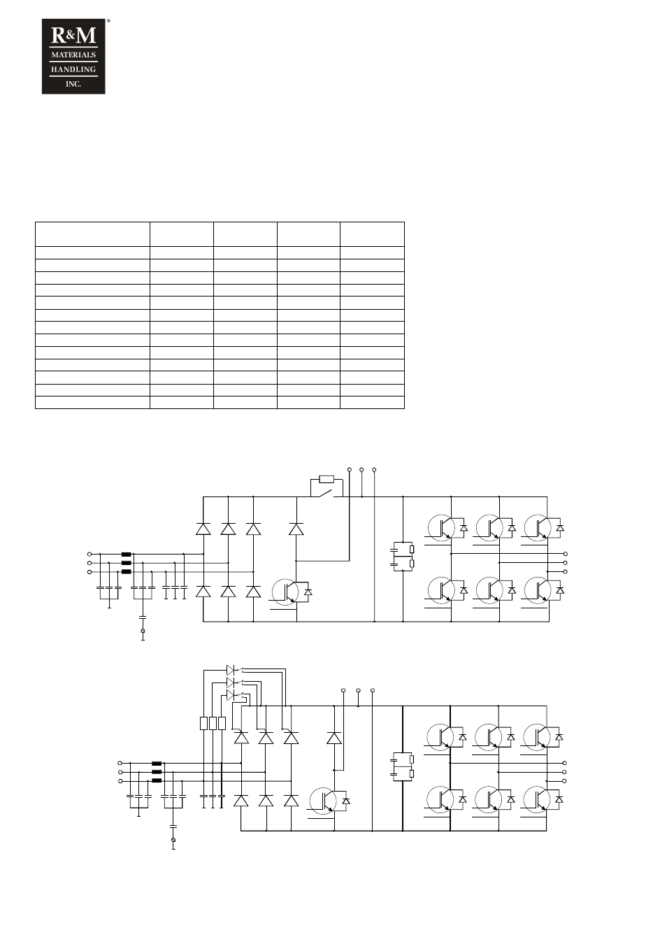
1.14 Inverter
Inverter (D2V) includes Power supply unit (PSU) and Control unit (CSU), which are separate parts. PSU
includes supply, brake resistor and motor connections. IGBTs are placed to PSU. Microprocessors and ASIC
are placed to CSU. Same CSU can be used in every power class.
D2V
In
1min
Imax
Weight
kg
Weight
lbs
D2V002NF1e000
6,5
10
6
13
D2V003NF1e000
8
12
6
13
D2V004NF1e000
10
15
6
13
D2V005NF1e000
13
20
6
13
D2V007NF1e000
18
27
10
22
D2V011NF1e000
24
36
10
22
D2V015NF1e000
32
48
20
44
D2V018NF1e000
42
63
20
44
D2V022NF1e000
48
72
20
44
D2V030NF1e000
60
90
37
82
D2V037NF1e000
75
113
37
82
D2V045NF1e000
90
135
37
82
D2V055NF1e000
110
165
61
135
e defines emission level ( 0 = EMC level 0, N = EMC level N/S )
The main circuit diagram of D2V002 – D2V005
L1
L2
L3
DC-
DC+
BR
B+
B-
U/T1
V/T2
W/T3
WH_G
WH_D
WL_G
WL_D
VH_G
VH_D
VL_D
UL_G
UL_D
BRK_G
BRK_D
UH_D
UH_G
VL_G
The main circuit diagram of D2V007 – D2V055
DC-
DC+
BR
B+
B-
WH_G
WH_D
WL_D
VH_G
VH_D
VL_G
VL_D
BRK_G
BRK_D
U/T1
V/T2
W/T3
L1
L2
L3
UH_D
UH_G
UL_G
UL_D
WL_G