4 buffer amplifier kae234, Kae234 connection with sensor bearing – R&M Materials Handling VARIABLE SPEED CONTROLS ControlMaster Plus Service Manual User Manual
Page 23
R&M Materials Handling, Inc.
4501 Gateway Boulevard
Springfield, Ohio 45502
P.: (937) 328-5100
FAX: (937) 325-5319
23/83
R&M Materials Handling, Inc. reserves the right to alter or amend the above information without notice.
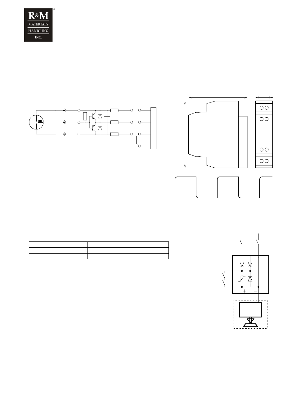
1.16.4 Buffer amplifier KAE234
The speed sensor (proximity switch or sensor bearing) is connected to inverter via KAE234 buffer amplifier. KAE234
must be located near the sensor (usually in the connection box of the hoist or the motor).
Without a buffer amplifier some faulty pulses could activate the speed supervision of inverter. Typically the problem would
be a momentary lack of pulses or oscillations at the sensor output. Usually the noise sensitivity increases when the
sensor temperature rises.
KAE234 connection with sensor bearing.
3
4
7
6
1
2
OUT
+24V
0V
:55
:51
:56
X1
+24V
EA+
0V
IN
V
E
R
T
E
R
WHITE
BLACK
+24V
A
0V
RED
:52
EA-
BROWN
GREEN
WHITE
79
69
20
1
2
3
4
5
6
7
8
Buffer amplifier pulse output can be measured
during driving. The picture beside presents the
pulse output.
0± 1V
24V± 1V
1.17 Brake controllers
1.17.1 REC12
Brake control unit REC12 is a line voltage half-wave rectifier for DC-brakes.
L2
L1-1
L1-2
a
b
K7
Brake
K7
K7
R
E
C
1
2
AC Line Voltage
K7
Voltage range
200...690Vac
Output voltage U
DC
Half wave 0.45 x U
AC
Maximum current
1.25Adc
When the brake is opened, the brake contactor K7 connects two phases of mains
voltage to terminals L1 and L2. In addition, the brake contactor shorts terminals a and b
thus making the DC-circuit.
To close the brake, the brake contactor disconnects the supply to terminals L1 and L2.
The released brake contactor also opens the brake coil DC-circuit, which speeds
closing of the brake. The purpose of the varistor there is overvoltage protection for K7
contacts and the brake coil.