Standard connection with sensor bearing – R&M Materials Handling VARIABLE SPEED CONTROLS ControlMaster Plus Service Manual User Manual
Page 20
R&M Materials Handling, Inc.
4501 Gateway Boulevard
Springfield, Ohio 45502
P.: (937) 328-5100
FAX: (937) 325-5319
20/83
R&M Materials Handling, Inc. reserves the right to alter or amend the above information without notice.
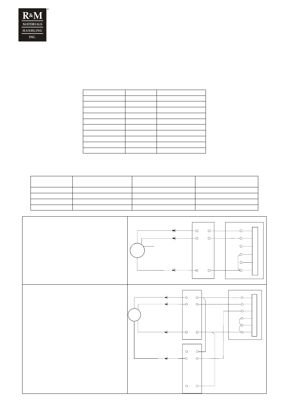
1.16 Speed sensors
1.16.1 Sensor bearing
Inverter needs information about the motor rotation speed for stall, speed difference and over speed supervision. Bearing
sensors are shown in the table below.
Motor type
Motor code
Pulses per revolution
MF10MA200
T1
32 or 48
MF10MB200
T2
32 or 48
MF10MC200
T3
32 or 48
MF11MA200
T4
64
MF11MB200
T5
64
MF13Z-200
T6
80
MF13ZA200
T7
80
MF13ZB200
T8
80
MF13ZC200
T9
80
MF13X-200
TA
80
Sensor bearing requires KAE234 buffer amplifier. If channel A+ is damaged, channel B+ can be used instead in
emergency situations. With Synchro, both channels must be connected.
Signal name
Sensor bearing
wire colour
Wire colour between KAE234
and motor plug
Terminal number
+24V
Red
Brown
KAE234:6
0V
Black
Green
KAE234:2
A+
White
White
KAE234:1
B+
Blue
Yellow
KAE234:1
Standard connection with sensor bearing.
:55
+24V
:51
EA+
:54
EB-
IN
V
E
R
T
E
R
black
+V
0V
red
:56
0V
:53
EB+
:52
EA-
G
white
A+
D2L
X1
KAE 234
6
1
2
3
4
7
blue
B+
BROWN
GREEN
WHITE
Standard connection with sensor bearing. Two
channels connected for Synchro.
:55
+24V
:51
EA+
:54
EB-
IN
V
E
R
T
E
R
:56
0V
:53
EB+
:52
EA-
D2L
X1
black
+V
0V
red
G
white
A+
KAE 234
6
1
2
3
4
7
blue
B+
BROWN
GREEN
WHITE
KAE 234
6
1
2
3
4
7
YELLOW