Reset switch – B&B Electronics VESP211 Series - Manual User Manual
Page 11
Section 2 - VESP211 Hardware
Vlinx VESR4x4 Serial Server
Page 11 of 66
Manual Documentation Number: VESP211-5011m
www.bb-elec.com/
www.bb-europe.com/
Note:
LEDs on the serial server are also used to indicate various Reset modes, as described in the
following section.
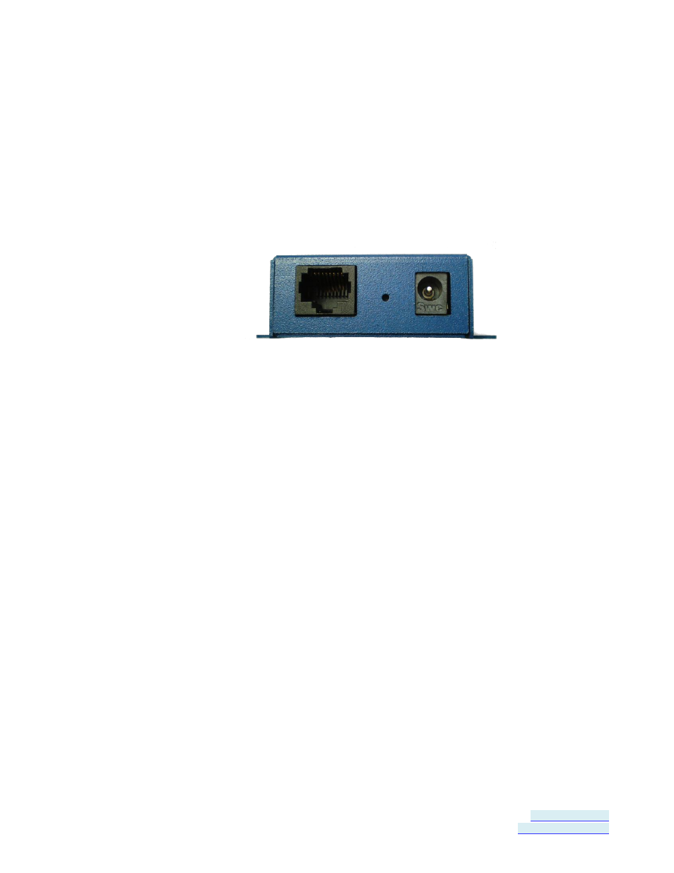
Reset Switch
A recessed momentary Reset switch is located on the side of the enclosure.
To activate the switch, insert a small plastic tool through the hole in the
enclosure and press lightly.
Figure 4.
Ethernet Connector, Reset Switch (recessed) and Power Connector
The Reset switch can be used to:
Initiate a Hardware Reset
Enter Console Mode
Reload factory defaults
Using the Reset Switch to Initiate a Hardware Reset
Hold the Reset switch in for 0 to 2 seconds. The Ready LED stops blinking
while the switch is being held in. The Serial LED illuminates while the switch is
being held in. Release the switch in less than two seconds or the serial server
will enter Console Mode.
Using the Reset Switch to Enter Console Mode
Hold the Reset switch for between two and ten seconds. The Ready LED stops
blinking while the switch is being held in. The Serial LED illuminates for the
first two seconds; then Serial LED goes out and the Ready LED illuminates.
Release the switch in less than 10 seconds or the serial server will reset to
factory default settings.