3 sector protection register – Rainbow Electronics AT45DQ321 User Manual
Page 23
23
AT45DQ321 [ADVANCE DATASHEET]
DS-45DQ321-031–DFLASH–12/2012
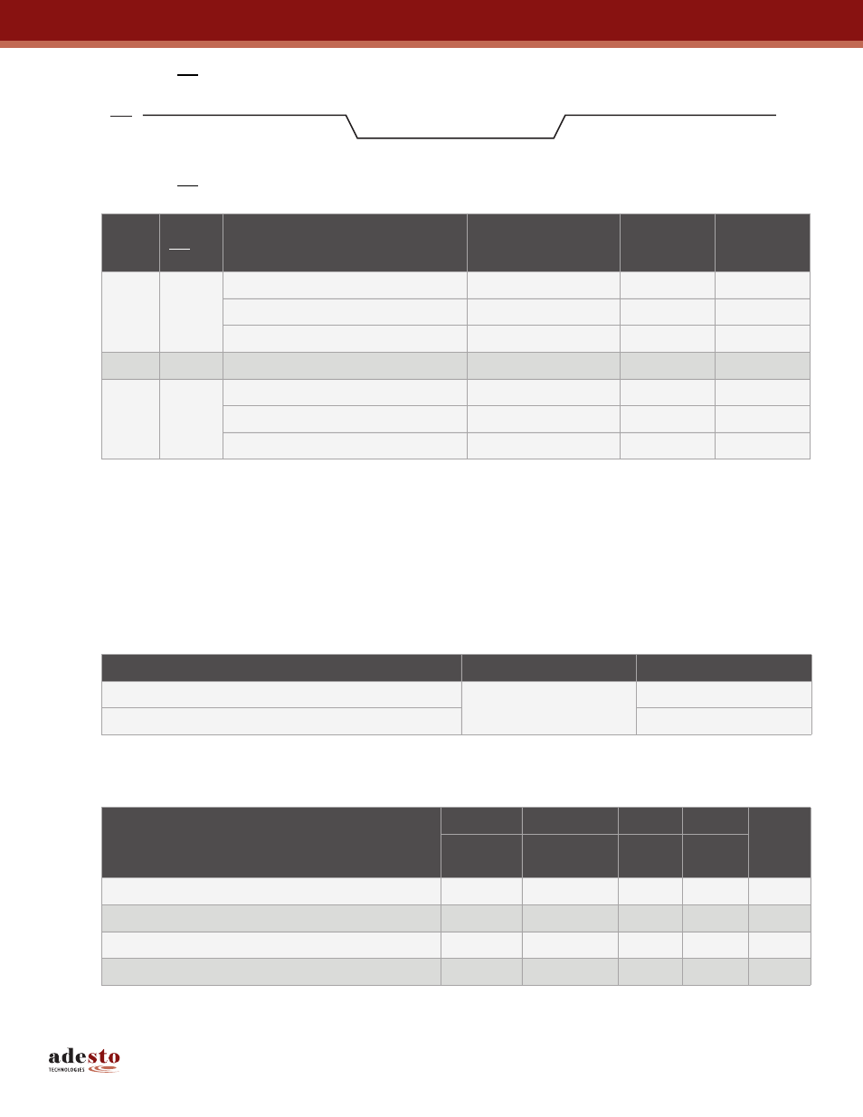
Figure 7-3. WP Pin and Protection Status
Table 7-3.
WP Pin and Protection Status
7.3
Sector Protection Register
The nonvolatile Sector Protection Register specifies which sectors are to be protected or unprotected with either the
software or hardware controlled protection methods. The Sector Protection Register contains 64 bytes of data, of which
byte locations 0 through 63 contain values that specify whether Sectors 0 through 63 will be protected or unprotected.
The Sector Protection Register is user modifiable and must be erased before it can be reprogrammed.
illustrates the format of the Sector Protection Register.
Table 7-4.
Sector Protection Register
Note:
1. The default values for bytes 0 through 63 are 00h when shipped from Adesto.
Table 7-5.
Sector 0 (0a, 0b) Sector Protection Register Byte Value
Note:
1. x = Don’t care
Time
Period
WP Pin
Enable Sector Protection Command
Disable Sector
Protection Command
Sector
Protection
Status
Sector
Protection
Register
1
High
Command Not Issued Previously
X
Disabled
Read/Write
—
Issue Command
Disabled
Read/Write
Issue Command
—
Enabled
Read/Write
2
Low
X
X
Enabled
Read
3
High
Command Issued During Period 1 or 2
Not Issued Yet
Enabled
Read/Write
—
Issue Command
Disabled
Read/Write
Issue Command
—
Enabled
Read/Write
WP
1
2
3
Sector Number
0 (0a, 0b)
1 to 63
Protected
FFh
Unprotected
00h
Bit 7:6
Bit 5:4
Bit 3:2
Bit 1:0
Data
Value
Sector 0a
(Page 0-7)
Sector 0b
(Page 8-127)
N/A
N/A
Sectors 0a and 0b Unprotected
00
00
XX
XX
0xh
Protect Sector 0a
11
00
XX
XX
Cxh
Protect Sector 0b
00
11
XX
XX
3xh
Protect Sectors 0a and 0b
11
11
XX
XX
Fxh