Adc noise canceler function – Rainbow Electronics AT90LS8535 User Manual
Page 71
71
AT90S/LS8535
1041H–11/01
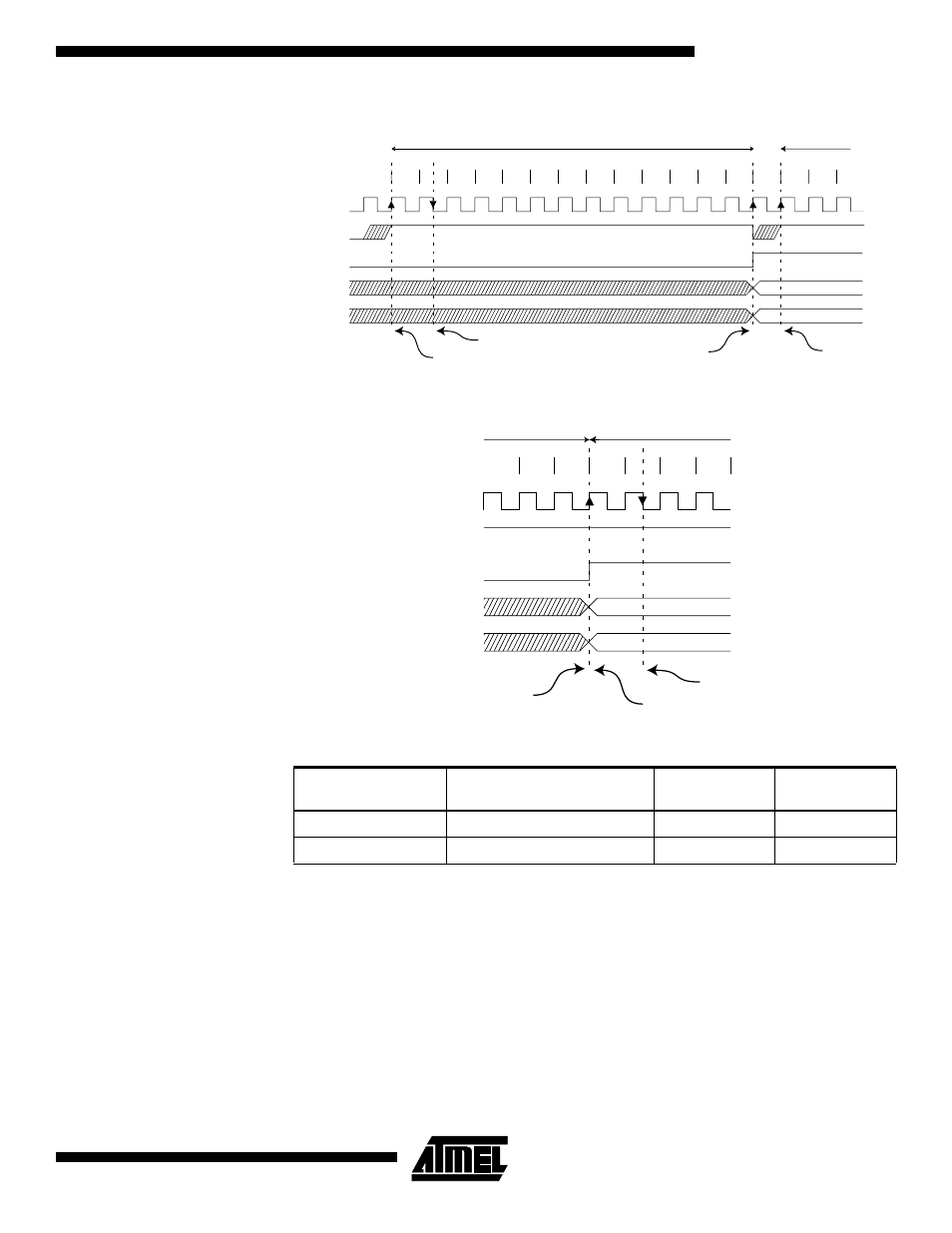
Figure 48. ADC Timing Diagram, Single Conversion
Figure 49. ADC Timing Diagram, Free Running Conversion
ADC Noise Canceler
Function
The ADC features a noise canceler that enables conversion during Idle Mode to reduce
noise induced from the CPU core. To make use of this feature, the following procedure
should be used:
1.
Make sure that the ADC is enabled and is not busy converting. Single Conver-
sion Mode must be selected and the ADC conversion complete interrupt must be
enabled.
ADEN = 1
ADSC = 0
ADFR = 0
ADIE = 1
Table 26. ADC Conversion Time
Condition
Sample and Hold (Cycles
from Start of Conversion)
Conversion
Time (Cycles)
Conversion
Time (µs)
Extended Conversion
14
25
125 - 500
Normal Conversion
14
26
130 - 520
1
2
3
4
5
6
7
8
9
10
11
12
13
Sign and MSB of result
LSB of result
ADC clock
ADSC
ADIF
ADCH
ADCL
Cycle number
1
2
One Conversion
Next Conversion
3
Sample & hold
MUX and REFS
update
Conversion
complete
MUX and REFS
update
11
12
13
Sign and MSB of result
LSB of result
ADC clock
ADSC
ADIF
ADCH
ADCL
Cycle number
1
2
One Conversion
Next Conversion
3
4
Conversion
complete
Sample & hold
MUX and REFS
update