Rainbow Electronics AT90LS8535 User Manual
Page 41
41
AT90S/LS8535
1041H–11/01
up-counting and down-counting values are reached simultaneously. When the prescaler
is in use (CS12..CS10
≠ 001 or 000), the PWM output goes active when the counter
reaches TOP value, but the down-counting compare match is not interpreted to be
reached before the next time the counter reaches the TOP value, making a one-period
PWM pulse.
Note:
X = A or B
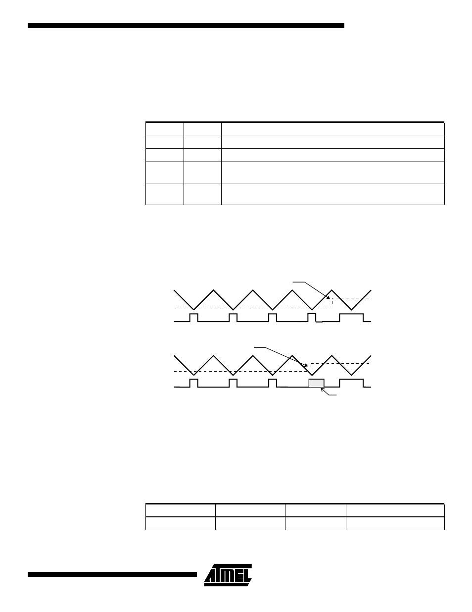
Note that in the PWM mode, the 10 least significant OCR1A/OCR1B bits, when written,
are transferred to a temporary location. They are latched when Timer/Counter1 reaches
the value TOP. This prevents the occurrence of odd-length PWM pulses (glitches) in the
event of an unsynchronized OCR1A/OCR1B write. See Figure 33 for an example.
Figure 33. Effects of Unsynchronized OCR1 Latching
During the time between the write and the latch operations, a read from OCR1A or
OCR1B will read the contents of the temporary location. This means that the most
recently written value always will read out of OCR1A/B.
When the OCR1A/OCR1B contains $0000 or TOP, the output OC1A/OC1B is updated
t o l o w o r h i g h o n t h e n e x t c o m p a r e m a t c h a c c o r d i n g t o t h e s e t t i n g s o f
COM1A1/COM1A0 or COM1B1/COM1B0. This is shown in Table 16.
Table 15. Compare1 Mode Select in PWM Mode
COM1X1
COM1X0
Effect on OCX1
0
0
Not connected
0
1
Not connected
1
0
Cleared on compare match, up-counting. Set on compare match,
down-counting (non-inverted PWM).
1
1
Cleared on compare match, down-counting. Set on compare match,
up-counting (inverted PWM).
Table 16. PWM Outputs OCR1X = $0000 or TOP
COM1X1
COM1X0
OCR1X
Output OC1X
1
0
$0000
L
Counter Value
Compare Value
PWM Output OC1X
Synchronized
OCR1X Latch
Counter Value
Compare Value
PWM Output OC1X
Unsynchronized
OCR1X Latch
Glitch
Compare Value changes
Note: X = A or B
Compare Value changes