Bit timer/counter2 – Rainbow Electronics AT90LS8535 User Manual
Page 42
42
AT90S/LS8535
1041H–11/01
Note:
X = A
In PWM mode, the Timer Overflow Flag1 (TOV1) is set when the counter advances from
$0000. Timer Overflow Interrupt1 operates exactly as in normal Timer/Counter mode,
i.e., it is executed when TOV1 is set, provided that Timer Overflow Interrupt1 and global
interrupts are enabled. This also applies to the Timer Output Compare1 flags and
interrupts.
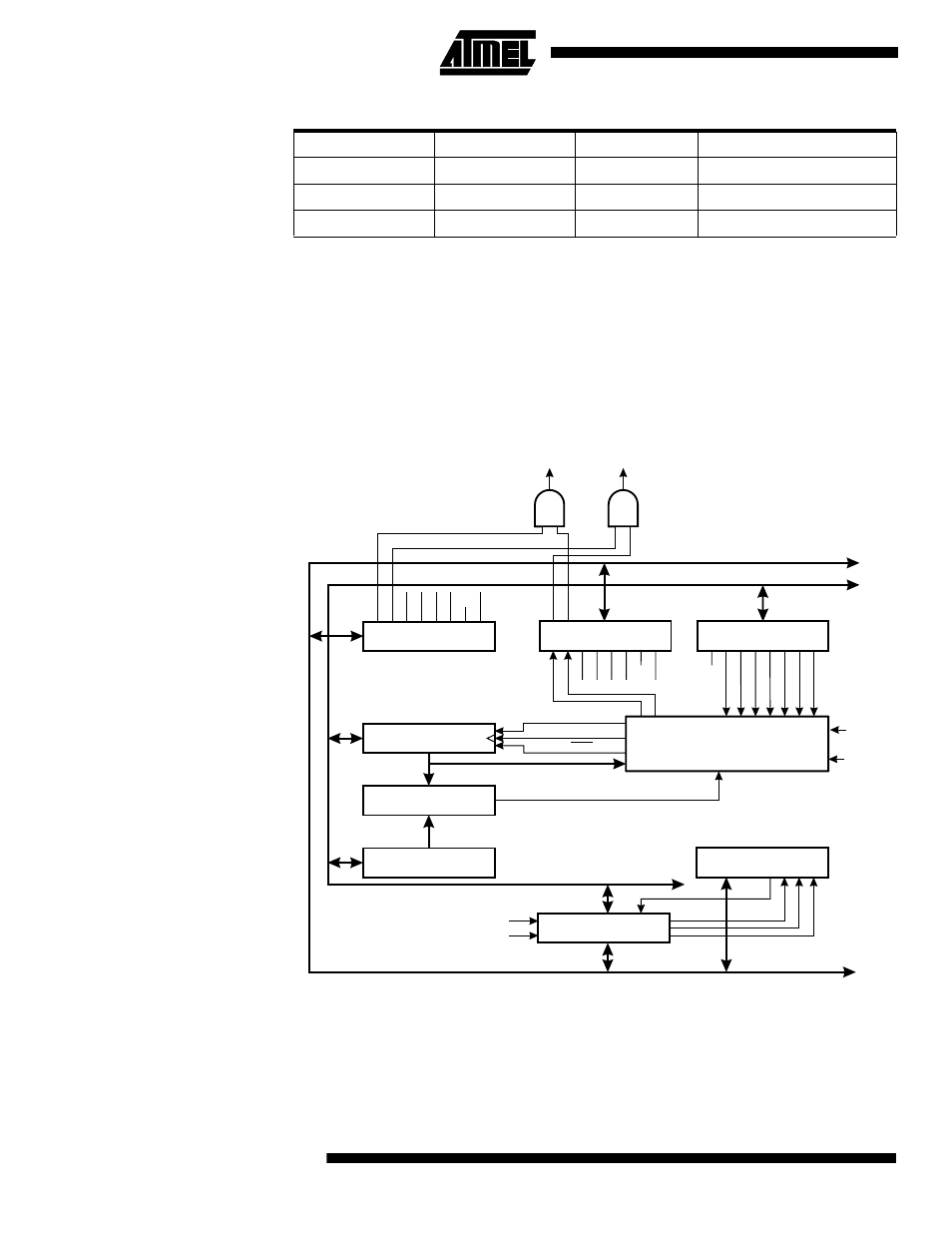
8-bit Timer/Counter2
Figure 34 shows the block diagram for Timer/Counter2.
Figure 34. Timer/Counter2 Block Diagram
The 8-bit Timer/Counter2 can select clock source from PCK2 or prescaled PCK2. It can
also be stopped as described in the specification for the Timer/Counter Control Register
(TCCR2).
The diffe rent statu s flag s (Overflow an d Com pare M atch) a re foun d in th e
Timer/Counter Interrupt Flag Register (TIFR). Control signals are found in the
1
0
TOP
H
1
1
$0000
H
1
1
TOP
L
Table 16. PWM Outputs OCR1X = $0000 or TOP
COM1X1
COM1X0
OCR1X
Output OC1X
8-BIT DATA BUS
8-BIT ASYNCH T/C2 DATA BUS
ASYNCH. STATUS
REGISTER (ASSR)
TIMER INT. FLAG
REGISTER (TIFR)
TIMER/COUNTER2
(TCNT2)
SYNCH UNIT
8-BIT COMPARATOR
OUTPUT COMPARE
REGISTER2 (OCR2)
TIMER INT. MASK
REGISTER (TIMSK)
0
0
0
7
7
7
T/C CLK SOURCE
UP/DOWN
T/C CLEAR
CONTROL
LOGIC
TOV0
TOV1
OCF1B
OCF1A
ICF1
TOV2
OCF2
OCF2
TOV2
TOIE0
TOIE1
OCIE1A
OCIE1B
TICIE1
TOIE2
OCIE2
OCR2UB
TC2UB
ICR2UB
TOSC1
CK
PCK2
T/C2 OVER-
FLOW IRQ
T/C2 COMPARE
MATCH IRQ
T/C2 CONTROL
REGISTER (TCCR2)
CS22
COM21
PWM2
AS2
CS21
COM20
CS20
CTC2
CK