1 sector protection register, 1 erase sector protection register command – Rainbow Electronics AT45DB081D User Manual
Page 14
14
3596N–DFLASH–11/2012
AT45DB081D
9.1
Sector Protection Register
The nonvolatile Sector Protection Register specifies which sectors are to be protected or unpro-
tected with either the software or hardware controlled protection methods. The Sector Protection
Register contains 16-bytes of data, of which byte locations 0 through 15 contain values that
specify whether sectors 0 through 15 will be protected or unprotected. The Sector Protection
Register is user modifiable and must first be erased before it can be reprogrammed.
illustrates the format of the Sector Protection Register.:
Note:
1. The default value for bytes 0 through 15 when shipped from Adesto is 00H
x = don’t care
9.1.1
Erase Sector Protection Register Command
In order to modify and change the values of the Sector Protection Register, it must first be
erased using the Erase Sector Protection Register command.
To erase the Sector Protection Register, the CS pin must first be asserted as it would be with
any other command. Once the CS pin has been asserted, the appropriate 4-byte opcode
sequence must be clocked into the device via the SI pin. The 4-byte opcode sequence must
start with 3DH and be followed by 2AH, 7FH, and CFH. After the last bit of the opcode sequence
has been clocked in, the CS pin must be deasserted to initiate the internally self-timed erase
cycle. The erasing of the Sector Protection Register should take place in a time of t
PE
, during
which time the Status Register will indicate that the device is busy. If the device is powered-
down before the completion of the erase cycle, then the contents of the Sector Protection Regis-
ter cannot be guaranteed.
The Sector Protection Register can be erased with the sector protection enabled or disabled.
Since the erased state (FFH) of each byte in the Sector Protection Register is used to indicate
that a sector is specified for protection, leaving the sector protection enabled during the erasing
of the register allows the protection scheme to be more effective in the prevention of accidental
programming or erasing of the device. If for some reason an erroneous program or erase com-
mand is sent to the device immediately after erasing the Sector Protection Register and before
the register can be reprogrammed, then the erroneous program or erase command will not be
processed because all sectors would be protected.
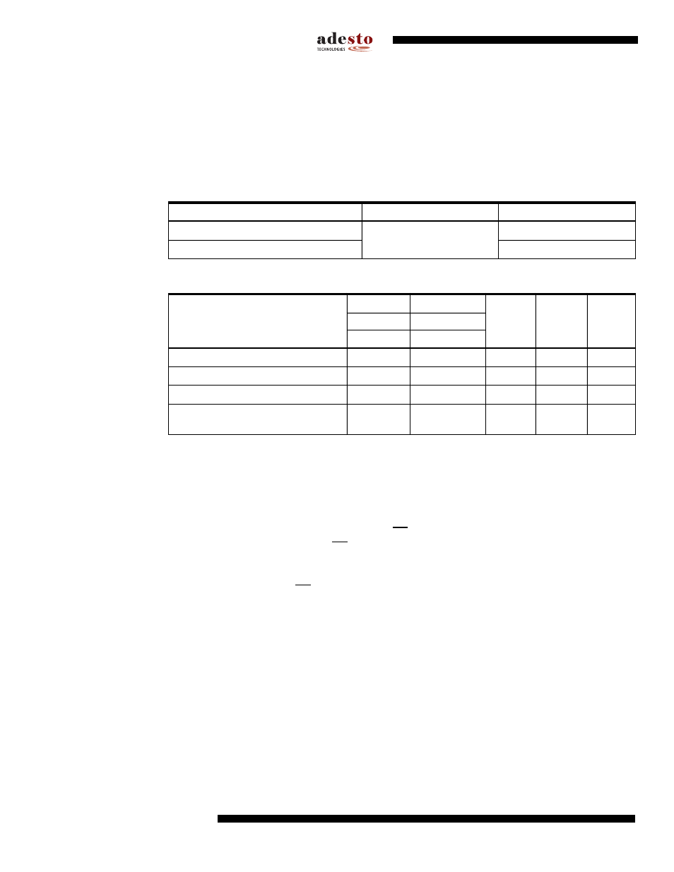
Table 9-2.
Sector Protection Register
Sector Number
0 (0a, 0b)
1 to 15
Protected
See
FFH
Unprotected
00H
Table 9-3.
Sector 0 (0a, 0b)
0a
0b
Bit 3, 2
Data
Value
(Page 0-7)
(Page 8-255)
Bit 7, 6
Bit 5, 4
Bit 1, 0
Sectors 0a, 0b Unprotected
00
00
xx
xx
0xH
Protect Sector 0a
11
00
xx
xx
CxH
Protect Sector 0b (Page 8-255)
00
11
xx
xx
3xH
Protect Sectors 0a (Page 0-7), 0b
(Page 8-255)
11
11
xx
xx
FxH