Parasite power, Bit lasered rom – Rainbow Electronics DS2422 User Manual
Page 9
DS2422
9 of 48
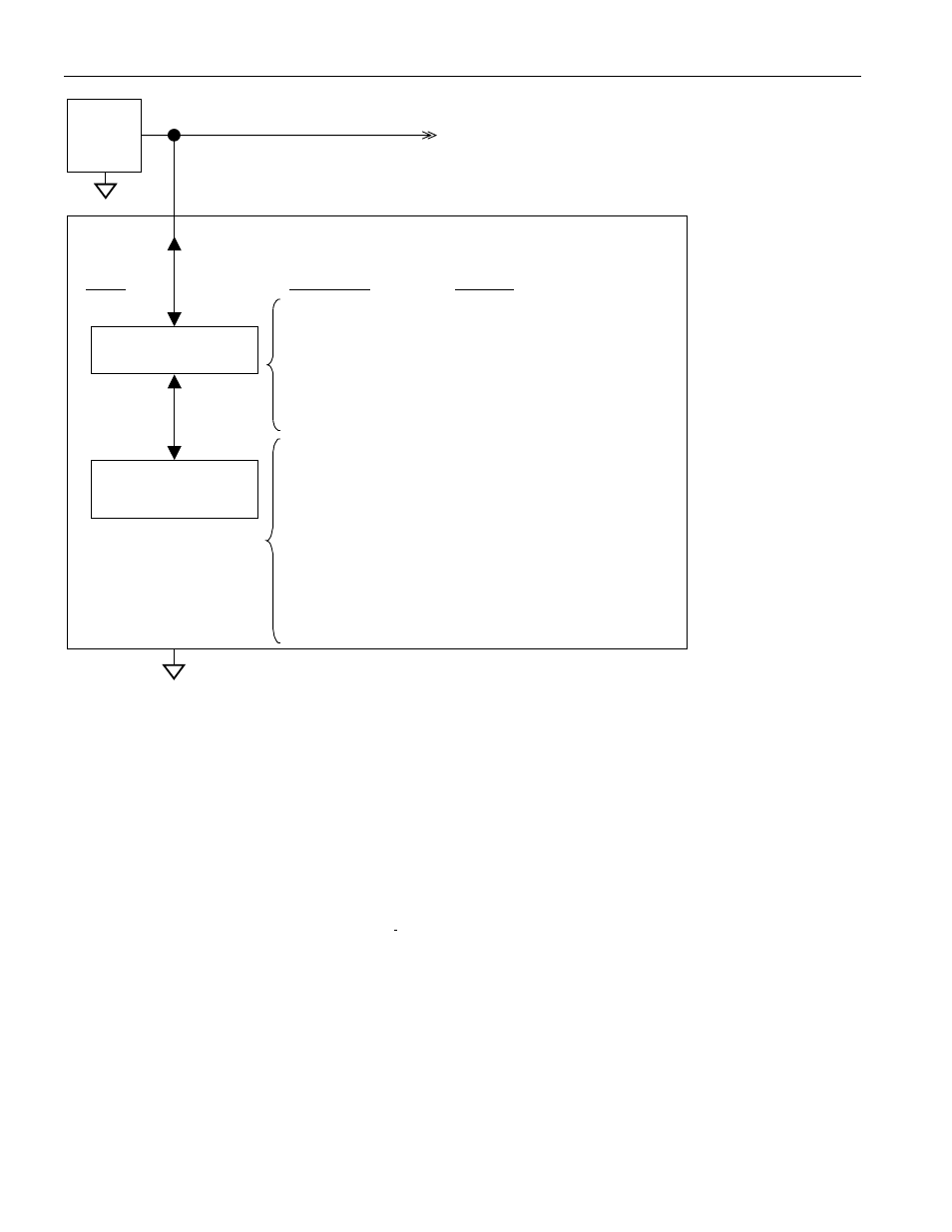
Figure 4. Hierarchical Structure for 1-Wire Protocol
1-Wire net
Other
Devices
BUS
Master
DS2422
Available
Commands:
Command
Level:
Data Field
Affected:
1-Wire ROM Function
Commands
DS2422-specific
Memory Function
Commands
Read ROM
Match ROM
Search ROM
Conditional Search ROM
Skip ROM
Resume
Overdrive Skip
Overdrive Match
64-bit ROM, RC-Flag
64-bit ROM, RC-Flag
64-bit ROM, RC-Flag
64-bit ROM, RC-Flag, Alarm Flags,
Search Conditions
RC-Flag
RC-Flag
RC-Flag, OD-Flag
64-bit ROM, RC-Flag, OD-Flag
Write Scratchpad
Read Scratchpad
Copy Scratchpad w/PW
Read Memory w/PW
Read Memory w/PW &
w/CRC
Clear Memory w/PW
Forced Conversion
Start Mission w/PW
Stop Mission w/PW
256-bit Scratchpad, Flags
256-bit Scratchpad
512 byte Data Memory, Registers,
Flags, Passwords
Memory, Registers, Passwords
Memory, Registers, Passwords
Mission Time Stamp, Mission Samples
Counter, Start Delay, Sample
Rate Register, Alarm Flags,
Passwords
Memory addresses 020C to 020Fh
Flags, Timestamp
Flags
PARASITE POWER
The block diagram (Figure 3) shows the parasite-powered circuitry. This circuitry “steals” power whenever the I/O
input is high. I/O provides sufficient power as long as the specified timing and voltage requirements are met. The
advantages of parasite power are two-fold: 1) by parasiting off this input, battery power is conserved; and 2) if the
battery is exhausted for any reason, the ROM may still be read.
64-BIT LASERED ROM
Each DS2422 contains a unique ROM code that is 64 bits long. The first 8 bits are a 1-Wire family code. The next
48 bits are a unique serial number. The last 8 bits are a CRC of the first 56 bits. See Figure 5 for details. The
1-Wire CRC is generated using a polynomial generator consisting of a shift register and XOR gates as shown in
Figure 6. The polynomial is X
8
+ X
5
+ X
4
+ 1. Additional information about the Dallas 1-Wire CRC is available in
Application Note 27 and in the Book of DS19xx iButton Standards.
The shift register bits are initialized to 0. Then starting with the least significant bit of the family code, one bit at a
time is shifted in. After the 8
th
bit of the family code has been entered, then the serial number followed by the
temperature range code is entered. After the range code has been entered, the shift register contains the CRC
value. Shifting in the 8 bits of CRC returns the shift register to all 0s.