Overview – Rainbow Electronics DS2422 User Manual
Page 8
DS2422
8 of 48
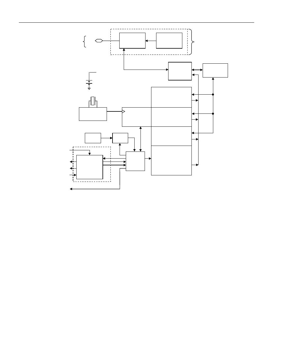
Figure 3. DS2422 Block Diagram
All circuitry is powered by the battery
unless otherwise specified
Internal
Timekeeping &
Control Reg. &
Counters
3V Lithium
General-Purpose
SRAM
(512 Bytes)
Register Pages
(64 Bytes)
Calibration Memory
(64 Bytes)
Datalog
Memory
8k Bytes
32.768kHz
Oscillator
Control
Logic
256-Bit
Scratchpad
Memory
Function
Control
ROM
Function
Control
64-Bit
Lasered
ROM
Parasite
Powered
Circuitry
1-Wire
Port
I/O
ADC1
Thermal
Sense
VPAD
CNVST
SCLK
SDATA
PUMP_ONZ
5V Pad
Structures
Powered by VBAT
OVERVIEW
The block diagram in Figure 3 shows the relationships between the major control and memory sections of the
DS2422. The device has six main data components: 1) 64-bit lasered ROM, 2) 256-bit scratchpad, 3) 512-byte
general-purpose SRAM, 4) two 256-bit register pages of timekeeping, control, status, and counter registers and
passwords, 5) 64 bytes of calibration memory, and 6) 8192 bytes of data-logging memory. Except for the ROM and
the scratchpad, all other memory is arranged in a single linear address space. The data-logging memory, counter
registers and several other registers are read-only for the user. Both register pages are write-protected while the
device is programmed for a mission. The password registers, one for a read password and another one for a
read/write password can only be written to, never read.
The hierarchical structure of the 1-Wire protocol is shown in Figure 4. The bus master must first provide one of the
eight ROM function commands: 1) Read ROM, 2) Match ROM, 3) Search ROM, 4) Conditional Search ROM, 5)
Skip ROM, 6) Overdrive-Skip ROM, 7) Overdrive-Match ROM or 8) Resume. Upon completion of an Overdrive
ROM command byte executed at standard speed, the device will enter Overdrive mode, where all subsequent
communication occurs at a higher speed. The protocol required for these ROM function commands is described in
Figure 14. After a ROM function command is successfully executed, the memory and control functions become
accessible and the master may provide any one of the eight available commands. The protocol for these memory
and control function commands is described in Figure 12. All data is read and written least significant bit first.