Step 2 – Rainbow Electronics DS2422 User Manual
Page 47
DS2422
47 of 48
STEP 2
During the setup, the device needs to learn the following information:
§
Time and Date
§
Sample Rate
§
Alarm Thresholds
§
Alarm Controls (Response to Conditional Search)
§
General Mission Parameters (e. g., channels to log and logging format, rollover, start mode)
§
Mission Start Delay
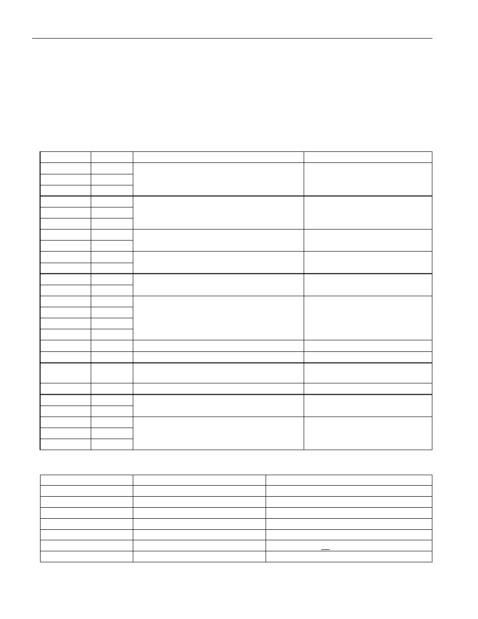
The following data will setup the DS2422 for a mission that logs temperature using 8-bit format. Such a mission
could last up to 56 days until the 8192-byte datalog memory is full.
ADDRESS
DATA
EXAMPLE VALUES
FUNCTION
0200h
00h
0201h
30h
15:30:00 hours
Time
0202h
15h
0203h
01h
0204h
04h
1
st
of April in 2002
Date
0205h
02h
0206h
0Ah
0207h
00h
Every 10 minutes (EHSS = 0)
Sample rate
0208h
52h
0°C low
Temperature Alarm
0209h
66h
10°C high
Threshold
020Ah
00h
External Data Alarm
020Bh
FFh
(Don’t care)
Threshold
020Ch
FFh
020Dh
FFh
020Eh
FFh
020Fh
FFh
(Don’t care)
Clock through read-only registers
0210h
02h
Enable high alarm
Temp. Alarm Control
0211h
FCh
Disabled
Data Alarm Control
0212h
01h
On (enabled), EHSS = 0 (low sample rate)
RTC Oscillator Control, sample
rate selection
0213h
C1h
Normal start; no rollover; 8-bit temp. log
General Mission Control
0214h
FFh
Clock through
0215h
FFh
(Don’t care)
read-only registers
0216h
5Ah
0217h
00h
90 minutes
Mission Start Delay
0218h
00h
With only a single DS2422 connected to the bus master, the communication of step 2 looks like this:
MASTER MODE
DATA (LSB FIRST)
COMMENTS
TX
(Reset)
Reset pulse
RX
(Presence)
Presence pulse
TX
CCh
Issue “skip ROM” command
TX
0Fh
Issue “write scratchpad” command
TX
00h
TA1, beginning offset=00h
TX
02h
TA2, address=0200h
TX
<25 data bytes>
Write 25 bytes of data to scratchpad