Mission control – Rainbow Electronics DS2422 User Manual
Page 17
DS2422
17 of 48
MISSION CONTROL
The DS2422 is set up for its operation by writing appropriate data to its special function registers, which are located
in the two register pages. The settings in the Mission Control Register determine whether temperature and/or
external data is logged, which format (8 or 16 bits) is to be used and whether old data may be overwritten by new
data, once the datalog memory is full. An additional control bit can be set to tell the DS2422 to wait with logging
data until a temperature alarm is encountered.
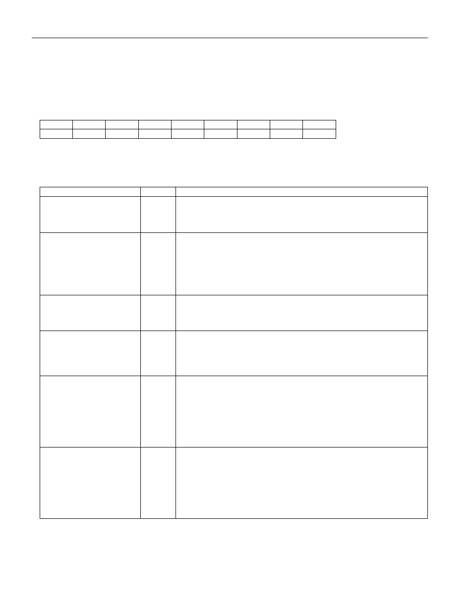
Mission Control Register Bitmap
ADDR
b7
b6
b5
b4
b3
b2
b1
b0
0213h
1
1
SUTA
RO
DLFS
TLFS
EDL
ETL
During a mission, there is only read access to this register. Bits 6 and 7 have no function. They always read 1 and
cannot be written to 0.
Register Details
BIT DESCRIPTION
BIT(S)
DEFINITION
ETL: Enable Temperature
Logging
b0
To set up the device for a temperature-logging mission, this bit must be
set to logic 1. To successfully start a mission, ETL or EDL must be 1. If
temperature logging is enabled, the recorded temperature values will
always be stored starting at address 1000h.
EDL: Enable Data Logging
b1
To set up the device for a data-logging mission (recording data from
serial data interface), this bit must be set to logic 1. To successfully
start a mission, ETL or EDL must be 1. If only data logging is enabled
(no temperature data), the recorded data values will be stored starting
at address 1000h. If both, temperature and data logging are enabled,
the recorded data values will begin at address 2000h (TLFS = DLFS)
or 1A00h (TLFS = 0; DLFS = 1) or 2400h (TLFS = 1; DLFS = 0).
TLFS: Temperature
Logging Format Selection
b2
This bit specifies the format used to store temperature readings in the
datalog memory. If this bit is 0, the data will be stored in 8-bit format. If
this bit is 1, the 16-bit format will be used (higher resolution). With 16-
bit format, the most-significant byte is stored at the lower address.
DLFS: Data Logging
Format Selection
b3
This bit specifies the format used to store data readings from the serial
data interface in the datalog memory. If this bit is 0, the data will be
stored in 8-bit format. If this bit is 1, the 16-bit format will be used
(higher resolution). With 16-bit format, the most-significant byte is
stored at the lower address.
RO: Rollover Control
b4
This bit controls whether, during a mission, the datalog memory is
overwritten with new data or whether data logging is stopped once the
datalog memory is full. Setting this bit to 1 enables the rollover and
data logging continues at the beginning, overwriting previously
collected data. If this bit is 0, the logging and conversions will stop
once the datalog memory is full. However, the RTC will continue to run
and the MIP bit will remain set until the Stop Mission command is
performed.
SUTA: Start Mission upon
Temperature Alarm
b5
This bit specifies whether a mission begins immediately (includes
delayed start) or if a temperature alarm will be required to start the
mission. If this bit is 1, the device will perform an 8-bit temperature
conversion at the selected sample rate and begin with data logging
only if an alarming temperature (high alarm or low alarm) was found.
The first datalog entry will be one sample period after the alarm
occurred. The Start Upon Temperature Alarm function is only available
if temperature logging is enabled (ETL = 1).