Mission start delay, Mission time stamp – Rainbow Electronics DS2422 User Manual
Page 19
DS2422
19 of 48
Register Details
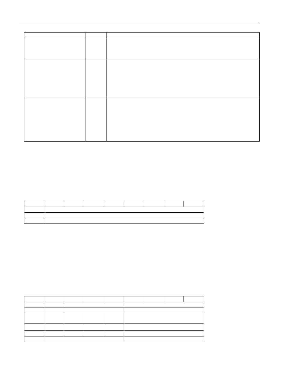
BIT DESCRIPTION
BIT(S)
DEFINITION
MIP: Mission In Progress
b1
If this bit reads 1 the device has been set up for a mission and this
mission is still in progress. The MIP bit returns from logic 1 to logic 0
when a mission is ended. See function commands Start Mission and
Stop Mission.
MEMCLR: Memory
Cleared
b3
If this bit reads 1, the Mission Time Stamp, Mission Samples Counter,
as well as all the alarm flags of the Alarm Status Register have been
cleared in preparation of a new mission. Executing the Clear Memory
command clears these memory sections. The MEMCLR bit will return
to 0 as soon as a new mission is started by using the Start Mission
command. The memory has to be cleared in order for a mission to
start.
WFTA: Waiting for
Temperature Alarm
b4
If this bit reads 1, the Mission Start upon Temperature Alarm was
selected and the Start Mission command was successfully executed,
but the device has not yet experienced the temperature alarm. This bit
is cleared after a temperature alarm event, but is not affected by the
Clear Memory command. Once set, WFTA remains set if a mission is
stopped before a temperature alarm occurs. To clear WFTA manually
before starting a new mission, set the high temperature alarm (address
0209h) to -40°C and perform a forced conversion.
MISSION START DELAY
The content of the Mission Start Delay Counter tells how many minutes will have to expire from the time
a mission
was started until the first measurement of the mission will take place (SUTA = 0) or until the device will start testing
the temperature for a temperature alarm (SUTA = 1). The Mission Start Delay is stored as an unsigned 24-bit
integer number. The maximum delay is 16777215 minutes, equivalent to 11650 days or roughly 31 years. If the
start delay is non-zero and the SUTA bit is set to 1, first the delay has to expire before the device starts testing for
temperature alarms to begin logging data.
Mission Start Delay Counter
ADDR
b7
b6
b5
b4
b3
b2
b1
b0
0216h
Delay Low Byte
0217h
Delay Center Byte
0218h
Delay High Byte
During a mission, there is only read access to these registers.
For a typical mission, the Mission Start Delay is 0. If a mission is too long for a single DS2422 to store all readings
at the selected sample rate, one can use several devices and set the Mission Start Delay for the second device to
start recording as soon as the memory of the first device is full, and so on. The RO-bit in the Mission Control
Register (address 0213h) must be set to 0 to prevent overwriting of collected data once the datalog memory is full.
MISSION TIME STAMP
The Mission Time Stamp indicates the date and time of the first logged temperature and/or data sample of the
mission. There is only read access to the Mission Time Stamp Register.
Mission Time Stamp Registers Bitmap
ADDR
b7
b6
b5
b4
b3
b2
b1
b0
0219h
0
10 Seconds
Single Seconds
021Ah
0
10 Minutes
Single Minutes
021Bh
0
12/24
20h.
AM/PM
10h.
Single Hours
021Ch
0
0
10 Date
Single Date
021Dh
CENT
0
0
10m.
Single Months
021Eh
10 Years
Single Years