Mission progress indicator, Other indicators, Security by password – Rainbow Electronics DS2422 User Manual
Page 20
DS2422
20 of 48
MISSION PROGRESS INDICATOR
Depending on settings in the Mission Control Register (address 0213h) the DS2422 will log temperature and/or
serial input data in 8-bit or 16-bit format. The description of the ETL and EDL bit explains where the device stores
data in its datalog memory. The Mission Samples Counter together with the starting address and the logging format
(8 or 16 bits) provides the information to identify valid blocks of data that have been gathered during the current
(MIP = 1) or latest mission (MIP = 0). See Datalog Memory Usage for an illustration.
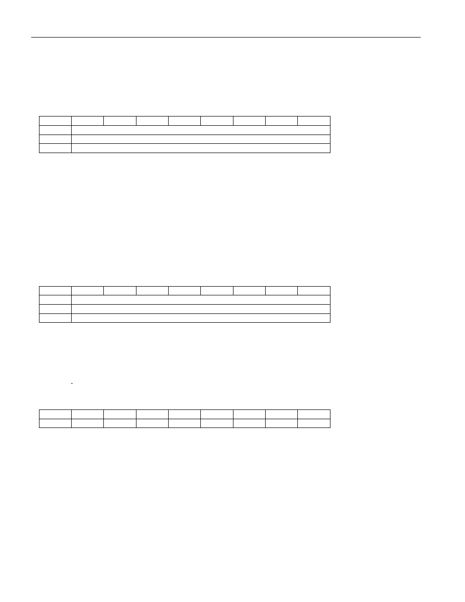
Mission Samples Counter Register Map
ADDR
b7
b6
b5
b4
b3
b2
b1
b0
0220h
Low Byte
0221h
Center Byte
0222h
High Byte
There is only read access to this register. Note that when both the internal temperature and serial input logging are
enabled, the two logs are counted as one event in the Mission Samples Counter and Device Samples Counter.
The number read from the Mission Samples Counter indicates how often the DS2422 woke up during a mission to
measure temperature and/or read data from its serial interface. The number format is 24-bit unsigned integer. The
Mission Samples Counter is reset through the Clear Memory command.
OTHER INDICATORS
The Device Samples Counter is similar to the Mission Samples Counter. During a mission this counter increments
whenever the DS2422 wakes up to measure and log data and when the device is testing for a temperature alarm in
SUTA mode. Between missions the counter increments whenever the Forced Conversion command is executed.
This way the Device Samples Counter functions like a gas gauge for the battery that powers the chip.
Device Samples Counter Register Map
ADDR
b7
b6
b5
b4
b3
b2
b1
b0
0223h
Low Byte
0224h
Center Byte
0225h
High Byte
There is only read access to this register.
The Device Samples Counter is reset to zero when the battery is connected to the V
BAT
pin. The number format is
24-bit unsigned integer. The maximum number that can be represented in this format is 16777215.
The Device Configuration Byte is used to allow the master to distinguish between the DS2422 chip and different
versions of iButtons based on this chip. With the DS2422, this byte always reads 00h.
Device Configuration Byte
ADDR
b7
b6
b5
b4
b3
b2
b1
b0
0226h
0
0
0
0
0
0
0
0
There is only read access to this register.
SECURITY BY PASSWORD
The DS2422 is designed to use two passwords that control read access and full access. Reading from or writing to
the scratchpad as well as the forced conversion command does not require a password. The password needs to be
transmitted right after the command code of the memory or control function. If password checking is enabled the
password transmitted is compared to the passwords stored in the device. The data pattern stored in the Password
Control register determines whether password checking is enabled.