Serial data input, Temperature alarm threshold examples, Figure 9a. serial interface timing – Rainbow Electronics DS2422 User Manual
Page 14: Figure 9b. serial interface setup and hold timing, Latest serial data reading result register bitmap
DS2422
14 of 48
Temperature Alarm Threshold Examples
J(°C)
TALM
hex
decimal
25.5
85h
133
-10.0
3Eh
62
SERIAL DATA INPUT
In addition to temperature, the DS2422 can log 8-bit or 16-bit digital information that it receives through its serial
interface. This interface is designed to directly connect to ADCs such as the MAX1086 or other circuits that use the
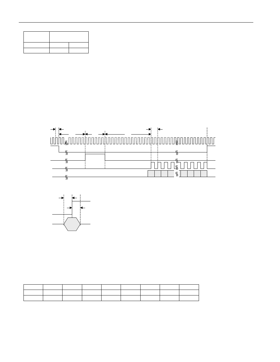
same interface timing. The general timing of the serial interface is shown in Figure 9. All timing is derived from an
on-chip ring oscillator, which generates the CLK signal. The CNVST signal is intended to start an
analog-to-digital
conversion. After the conversion is completed, the SCLK signal becomes active and on its rising edge clocks the
digital value into the DS2422. The PUMP_ONZ signal can activate a MAX619 charge pump to convert the 3V
battery voltage of the DS2422 into 5V, for example, to power additional circuitry.
Figure 9A. Serial Interface Timing
PUMP_ONZ
CNVST
SCLK
SDATA
CLK
B15 B14 B13 B12 b4 B3 B2 B1 B0
t
RING
t
SP
t
CPW
t
SCH
t
SCP
Figure 9B. Serial Interface Setup and Hold Timing
t
SDH
t
SDS
SCLK
SDATA
Data
Valid
The serial interface becomes active whenever the DS2422 executes a Forced Conversion command (see
Memory/Control Function Commands) or during a mission, if the device is set up to log data from its serial
interface. Regardless of its setup, the DS2422 always reads 16 bits from its serial input. The 16-bit result of the
latest serial reading is found at address 020Eh (low byte) and 020Fh (high byte). The first bit read through the
serial interface is always found as B15 at address 020Fh. If an ADC generates less than 16 bits, the internal weak
pulldown of the SDATA pin makes the missing bits read zero.
Latest Serial Data Reading Result Register Bitmap
ADDR
b7
b6
b5
b4
b3
b2
b1
b0
020Eh
B7
B6
B5
B4
B3
B2
B1
B0
LOW
020Fh
B15
B14
B13
B12
B11
B10
B9
B8
HIGH
During a mission, if data logging from the serial input is enabled, the HIGH byte (B15 to B8) is always recorded.
The LOW byte (B7 to B0) is only recorded if the DS2422 is set up for 16-bit logging of serial input data.
The algorithm to convert the digital reading from the serial interface into a physical unit depends on the circuit that
provides the data to the DS2422. This algorithm needs to be reversed when calculating values for the alarm