Figure 1. simple temperature logger – Rainbow Electronics DS2422 User Manual
Page 7
DS2422
7 of 48
under the control of SCLK. The DS2422 will activate its alarm output if the measured temperature or serial-input
data reaches a user-programmed high or low alarm threshold. This alarm then can be used to shut down the
equipment and enforce a service call. In contrast to microprocessor-based data loggers, the DS2422 does not
require any firmware development. Software for setup and data retrieval through the 1-Wire interface is available
for free download from the iButton website (
www.ibutton.com
). This software also includes drivers for the serial and
USB port 1-Wire interfaces of a PC, and routines to access the general-purpose memory for storing application or
equipment-specific data files.
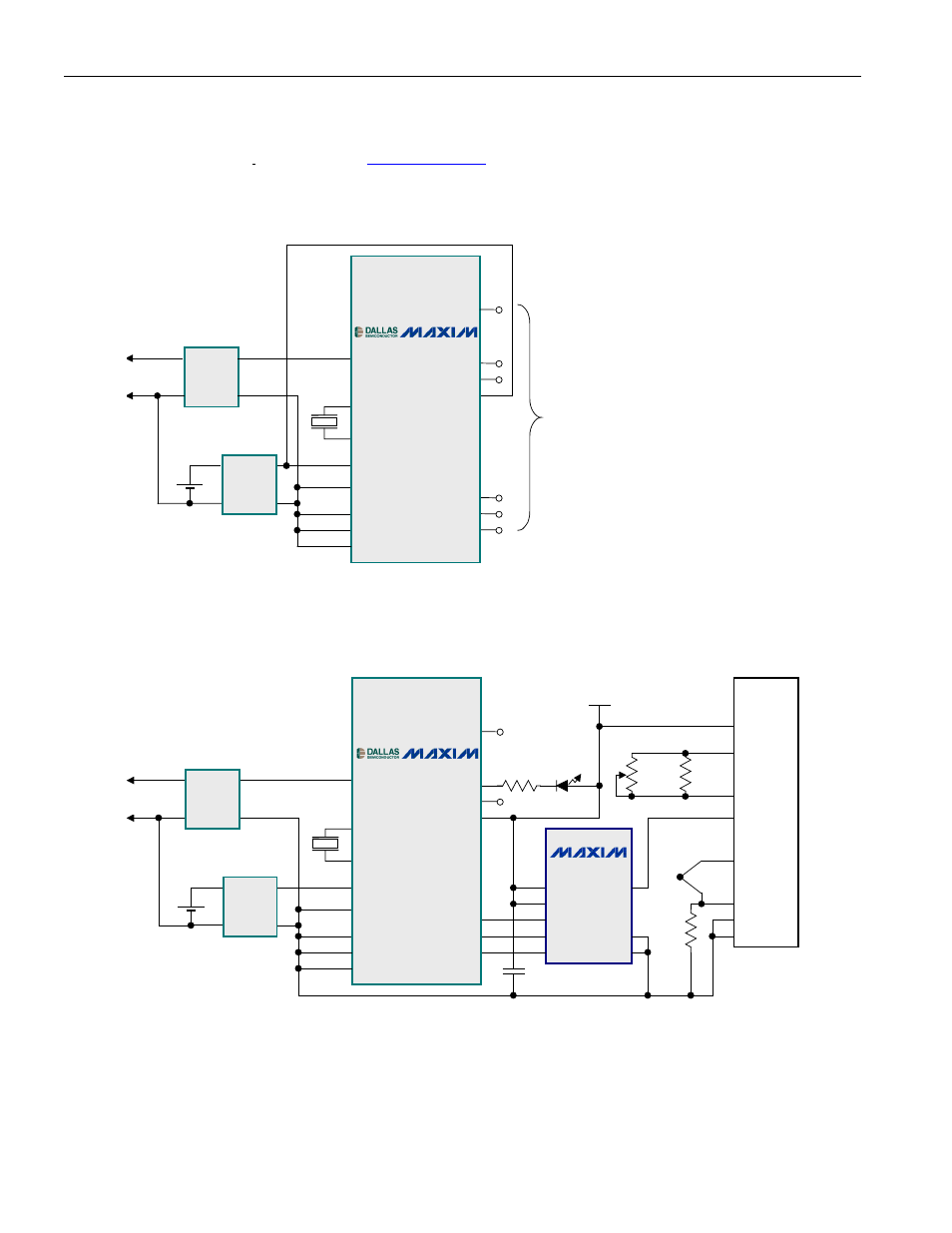
Figure 1. Simple Temperature Logger
KDS
SM14J
32768Hz
1-Wire
GND
Leave
open
BR1225R
Lithium
1
2
6
5
IC2
DS9503
1
2
6
5
IC3
DS9503
SDATA
SCLK
CNVST
AGND
GND
VBAT
VPAD
X2
IO
PUMP_ONZ
ALARM
CLK_TEST
TEST_EXT
OSC_TEST
X1
IC1
DS2422
SDATA
SCLK
CNVST
AGND
GND
VBAT
VPAD
X2
IO
PUMP_ONZ
ALARM
X1
TEST_SPLY
TEST_RX
TEST_CG
Figure 2. Temperature and Voltage Logger With Thermocouple
D1
1.5V LED
C1
0.1
mF
5V
1-Wire
GND
Leave
open
BR1225R
Lithium
KDS
SM14J
32768Hz
Thermocouple
Type E, J, K, N
R1
470
W
R3
2k
R4
2.2k
W
R2
200k
7
8
1
6
3
2
5
4
IC3
INA122
V-
Ref
Vin-
Vin+
Vo
RG
RG
V+
1
2
6
5
IC4
DS9503
1
2
6
5
IC5
DS9503
IC2
MAX1086
DOUT
SCLK
CNVST
REF
VDD
GND
AIN2
AIN1
1
5
6
8
7
2
3
4
SDATA
SCLK
CNVST
AGND
GND
VBAT
VPAD
X2
IO
PUMP_ONZ
ALARM
CLK_TEST
TEST_EXT
OSC_TEST
X1
IC1
DS2422
SDATA
SCLK
CNVST
AGND
GND
VBAT
VPAD
X2
IO
PUMP_ONZ
ALARM
TEST_CG
X1
TEST_SPLY
TEST_RX
Note: When using a positive/negative thermocouple, an offset voltage can be utilized through the Ref input of the
INA122 amplifier. This voltage shifts the 0V output of the amplifier up the amount equal to the offset voltage
allowing negative voltages to be read in the positive range of the MAX1086. This offset voltage may be obtained
through a simple resistor divider network (not shown).