56 mhz type b rf reader – Rainbow Electronics AT88RF1354 User Manual
Page 41
13.56 MHz Type B RF Reader
41
8547A
−RFID−10/08
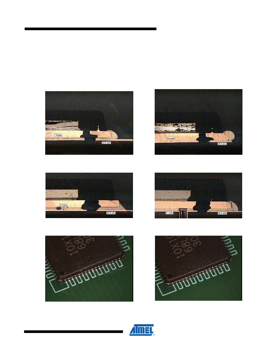
The fillet formation is also a function of the PCB land size, the printed solder volume, and the package standoff height.
Since there is only limited solder available, higher standoff (controlled by the paste coverage on the thermal pad) may
not leave enough solder for fillet formation. Conversely, if the standoff is too low, large convex shape fillets may form.
This is shown in Figure D-7. Since center pad coverage and via type were shown to have the greatest impact on the
standoff height, the volume of solder necessary to create optimum fillet varies. The package standoff height and the
PCB pads size will establish the required volume.
Figure D-7. Solder fillet shape for various standoff heights
37% Paste Coverage, Plugged Via,
1.4 mil Standoff
37% Paste coverage, Encroached Via,
0.6 mil Standoff
50% Paste Coverage, Plugged Via,
2.9 mil Standoff
81% Paste Coverage, Encroached Via,
2.1 mil Standoff
Large PCB Pads, 81% Paste Coverage,
Plugged Vias
Small PCB Pads, 81% Paste Coverage,
Plugged Vias