56 mhz type b rf reader – Rainbow Electronics AT88RF1354 User Manual
Page 32
32
13.56 MHz Type B RF Reader
8547A
−RFID−10/08
Appendix B.
The SPI Serial Interface
The SPI Interface mode is selected by shorting the ISEL pin to V
CC
. Six microcontroller pins are required to operate
AT88RF1354 in SPI mode. The ISTAT signal is used for handshaking between the microcontroller and RF reader.
B.1.
SPI Interface
The AT88RF1354 SPI interface operates as a slave device in SPI mode 0. In SPI mode 0 the polarity and phase of
the serial clock in relation to the data is as follows:
SCK is low when IDLE.
Incoming data on SDI is sampled on the positive edge of SCK.
Outgoing data on SDO is setup on the negative edge of SCK. (The host microcontroller samples SDO on the
positive edge of SCK)
ISTAT reports the serial interface status to the microcontroller.
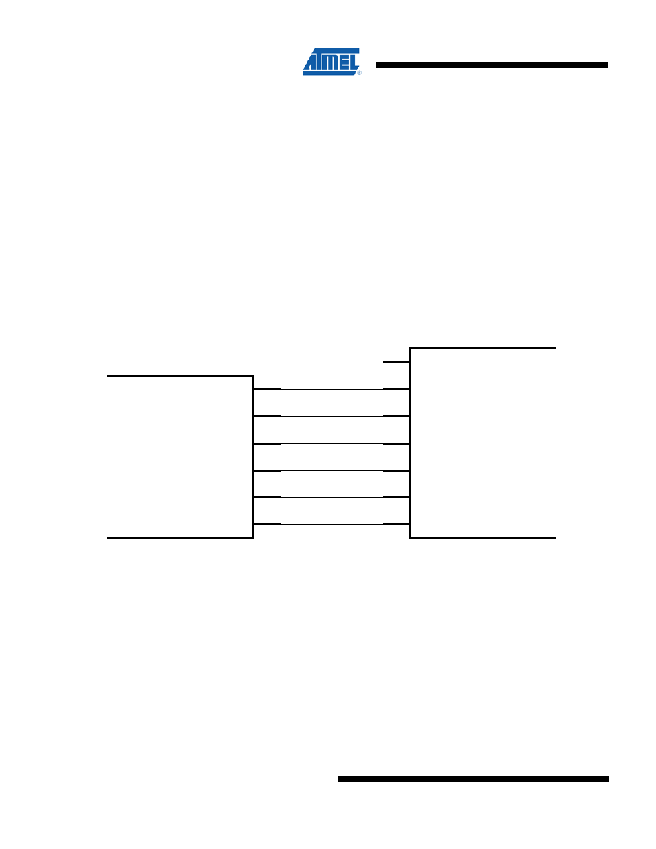
Figure B-1. Serial Interface wiring to SPI Microcontroller
Reader IC
AT88RF1354
(SPI Slave)
output
ResetB
ISEL
VCC
input
SCK
SDI
SDO
SSB
Istat
Microcontroller
(SPI Master)
SCK
MOSI
MISO
SSB
A high level on the ISTAT pin signals the host microcontroller that a byte of data is ready to be read from the
AT88RF1354 serial interface. If another byte is immediately available on the serial port, ISTAT will go low for 150 uS,
then return high. ISTAT will remain high until the last bit of the byte is read, when it will return low. All data must be
clocked out of the AT88RF1354 before it can receive a command.