56 mhz type b rf reader, D.4.4. stencil thickness and solder paste – Rainbow Electronics AT88RF1354 User Manual
Page 40
40
13.56 MHz Type B RF Reader
8547A
−RFID−10/08
D.4.4.
Stencil Thickness and Solder Paste
A stencil thickness of 0.125 mm is recommended for 0.4 and 0.5 mm pitch parts. A laser-cut, stainless steel stencil is
recommended with electro-polished trapezoidal walls to improve the paste release. Since not enough space is
available underneath the part after reflow, it is recommended that the “No Clean”, Type 3 paste be used for mounting
QFN packages. Nitrogen purge is also recommended during the reflow.
D.4.5.
Solder Joint Standoff Height and Fillet Formation
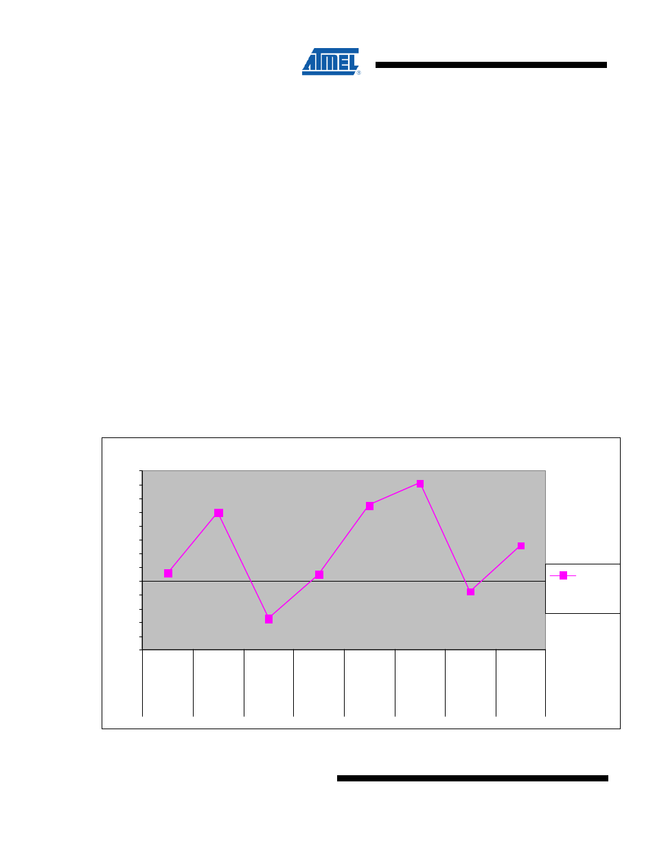
The solder joint standoff is a direct function of the amount of paste coverage on the thermal pad and the type of vias
used for QFNs with the exposed pad at the bottom. Board mounting studies sponsored by Amkor ® have clearly
shown that the package standoff increases by increasing the paste coverage and by using plugged vias in the
thermal pad region. This is shown in Figure D-6. below.
The standoff height varies by the amount of solder that wets or flows into the PTH via. The encroached via provides
an easy path for solder to flow into the PTH and decreases the package standoff height while the plugged via
impedes the flow of solder into the via due to the plugged via's closed barrel end. In addition, the number of vias and
their finished hole size will also influence the standoff height for encroached via design. The standoff height is also
affected by the paste type, the reactivity of the solder paste used during assembly, the PCB thickness, the copper
thickness, the surface finish, and the reflow profile.
To achieve 50 micron thick solder joints, which help in improving the board level reliability, it is recommended that
that the solder paste coverage be at least 50% for the plugged vias and 75% for the encroached via types.
The peripheral solder joint fillets formation is also driven by multiple factors. It should be realized that only the bottom
surface of the leads are plated with solder and not the ends. The bare Cu on the side of the leads may oxidize if the
packages are stored in an uncontrolled environment. It is, however, possible that a solder fillet will be formed
depending on the solder paste (flux) used and the level of oxidation.
Figure D-6. Standoff height as a function of via type and paste coverage.
Standoff Height as a function of Via Type & Center Pad Solder Paste Coverage
0
0.25
0.5
0.75
1
1.25
1.5
1.75
2
2.25
2.5
2.75
3
3.25
PLUGGED
VIA @ 37%
PASTE
COVERAGE
PLUGGED
VIA @67%
PASTE
Coverage
ENCROACH
VIA @ 37%
PASTE
Coverage
ENCROACH
VIA @67 %
Paste
Coverage
PLUGGED
VIA @ 50%
PASTE
Coverage
PLUGGED
VIA @ 81%
PASTE
Coverage
ENCROACH
VIA @ 50%
PASTE
Coverage
ENCROACH
VIA @ 81%
PASTE
Coverage
Standoff
Height
(mils)
48 IO
68 IO
48 IO
48 IO
48 IO
68 IO
68 IO
68 IO