56 mhz type b rf reader – Rainbow Electronics AT88RF1354 User Manual
Page 11
13.56 MHz Type B RF Reader
11
8547A
−RFID−10/08
6.2.
Digital Pin Descriptions
6.2.1.
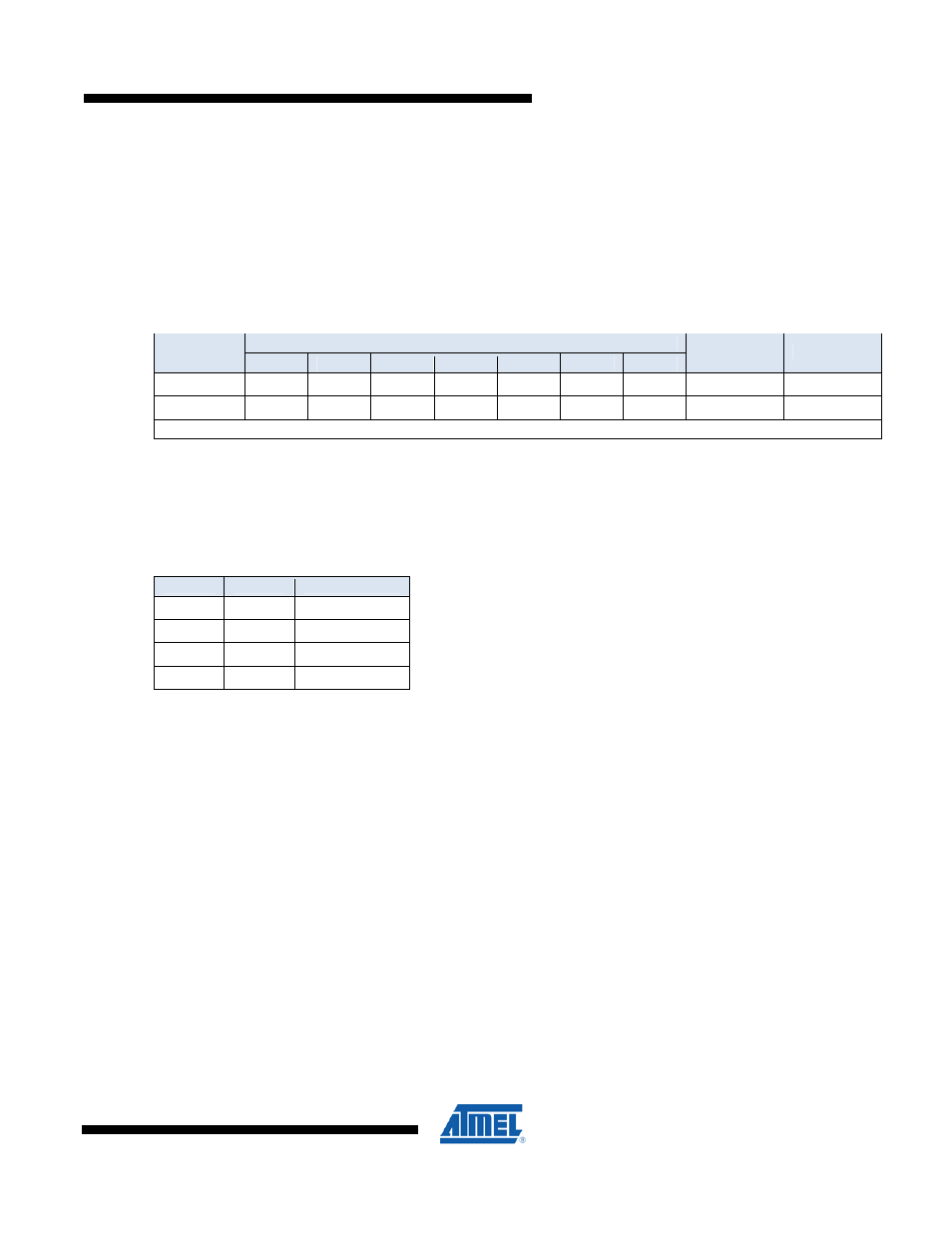
ADDR [20]
TWI device address select input pin. Selects between two TWI device addresses as shown in Table 4. In SPI
communication mode this pin should be connected to Vss.
Table 4. TWI Device Address
TWI Device Address
ADDR Pin
Bit 6
Bit 5
Bit 4
Bit 3
Bit 2
Bit 1
Bit 0
TWI_R
TWI_W
V
SS
0 1 0 1 0 0 0 $51
$50
V
CC
1 1 0 1 0 1 0 $D5
$D4
All other values are NOT supported
6.2.2.
CLK0 [8]
Clock Out pin. The PLL register selects the frequency of the clock which is output on this pin for use by external
circuits. The default CLKO frequency is 1.978 MHz. If the clock is not needed, then the CLKO output should be
disabled by programming the ENB bit of the PLL register to one.
Table 5. CLKO Output Frequency Options
Bit 1
Bit 0
CLKo Frequency
0 0 1.978
MHz
0 1 3.955
MHz
1 0 7.910
MHz
1 1 15.82
MHz
6.2.3.
ISEL [10]
Interface Select input pin. Selects TWI communications when low. SPI communication mode 0 is selected when high.
6.2.4.
Istat [12]
Interface Status output pin. Istat is the serial interface handshaking signal. A high level on Istat indicates that a byte
of data is ready to read from the serial interface port. A low level on Istat indicates that the serial interface buffer is
empty.
Note: Use of Istat for serial communications control is mandatory, and the AT88RF1354 will not accept commands
from the host microcontroller when Istat is high.
6.2.5.
ResetB [9]
Reset Bar input pin. A low on ResetB causes the device to reset. ResetB must be pulled high by the host
microcontroller and/or by an external resistor to V
CC
when the device is in use.
6.2.6.
SCK [14]
Serial Clock input pin. In both SPI and TWI serial communication modes this pin is used as the serial interface clock.