56 mhz type b rf reader, Standby mode timing – Rainbow Electronics AT88RF1354 User Manual
Page 19
13.56 MHz Type B RF Reader
19
8547A
−RFID−10/08
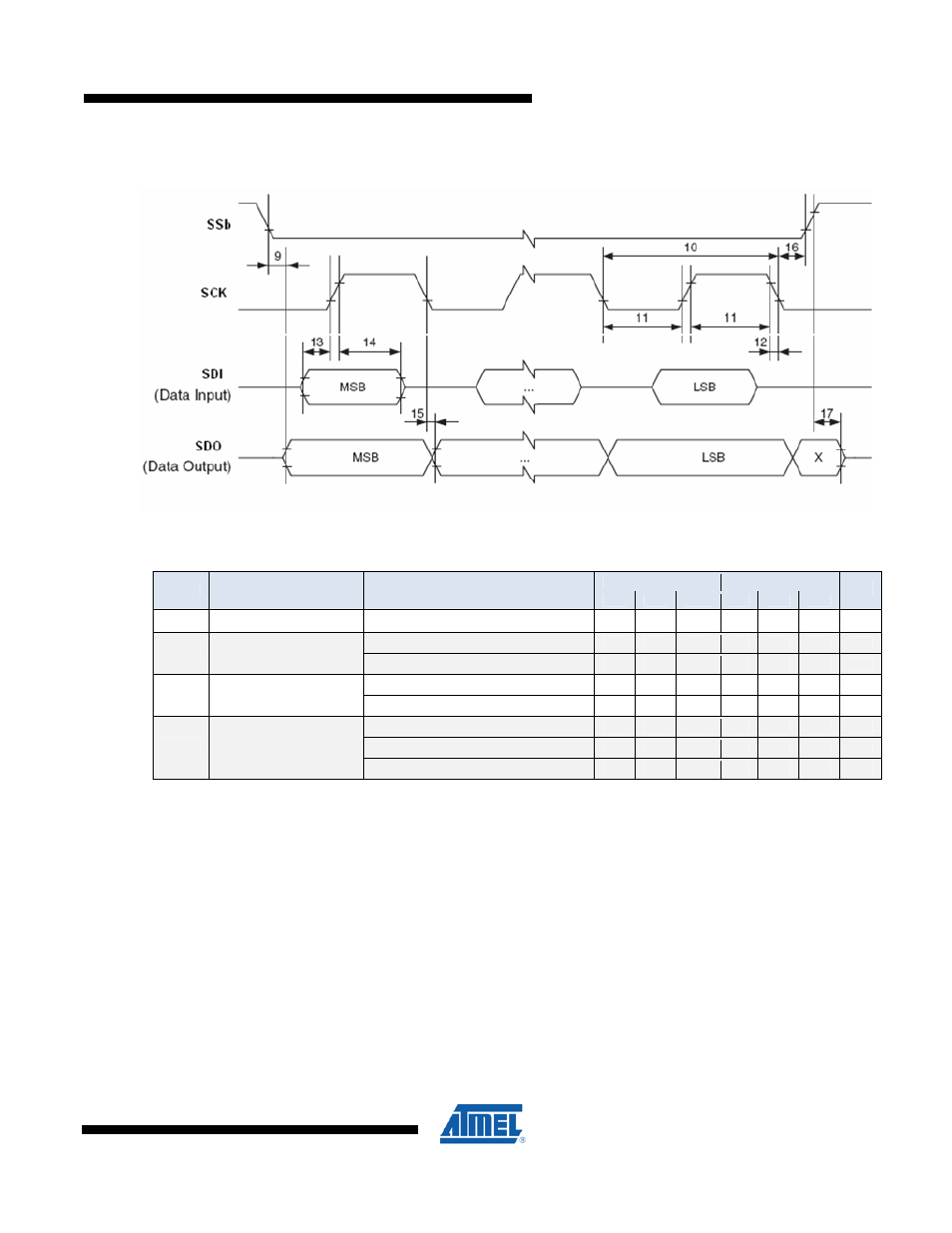
Figure 5.
SPI Interface timing requirements
Standby Mode Timing
Tc = -40° to +85° C (unless otherwise noted)
(1)
V
CC
= 3.0 to 3.6 V
V
CC
= 4.5 to 5.5 V
Symbol
Parameter
Condition
Min
Typical
Max
Min Typical
Max
Units
t
OSC
Crystal Oscillator start-up time Leaving OSC disabled Standby
(3)
uS
Entering OSC enabled Standby
(2)
uS
t
SDBY
Standby Mode Enable Time
Entering OSC disabled Standby
(3)
uS
Leaving OSC enabled Standby
(2)
uS
t
WAKE
Exit Standby Mode Time
Leaving OSC disabled Standby
(3)
uS
Leaving CLKO disabled Standby
(4)
uS
Leaving CLKO, PLL disabled Standby
(5)
uS
t
CLKO
CLKO start-up time
Leaving CLKO, PLL, OSC disabled Standby
(6)
uS
Note: 1. Typical values at 25° C. Maximum values are characterized values and not test limits in production.
2. OSC enabled Standby mode: PLL Register bit SL0 = 0 b.
3. OSC disabled Standby mode: PLL Register bit SL0 = 1 b.
4. CLKO disabled Standby mode: PLL Register bit ENB = 1 b.
5. CLKO disabled and PLL disabled Standby mode: PLL Register bits ENB = 1 b and SL0 = 1 b.
6. CLKO disabled, PLL disabled, and OSC disabled Standby mode: PLL Register bits ENB = 1 b
and SL0 = 1 b and SL1 = 1 b.
All values are preliminary and will be updated after characterization.