Rainbow Electronics MAX6963 User Manual
Page 9
MAX6960–MAX6963
4-Wire Serially Interfaced
8 x 8 Matrix Graphic LED Drivers
_______________________________________________________________________________________
9
display panel to be driven easily and intuitively by multi-
ple MAX6960s using 8 x 8 cathode-row matrix digits. The
MAX6960s in a display-driver design not only share the
host 4-wire interface, but they also share a local 3-wire
interface that is not connected to the host. The local 3-
wire interface works with the user’s driver settings to con-
figure all the MAX6960s to appear to the host interface as
one contiguous memory-mapped driver.
The pixel level-intensity control uses frame modulation.
Pixels are enabled and disabled on a frame-by-frame
basis over a 12-frame super frame (Table 5). The effec-
tive pixel frame duty cycle within a super frame sets each
pixel’s effective intensity. The 12-frame period of a super
frame allows arithmetic and geometric intensity scales to
be mixed on the same driver. This allows the user to set
up an RGY display with a different color scale for red and
RED
DRIVER0
GREEN
GREEN
GREEN
GREEN
GREEN
GREEN
GREEN
GREEN
GREEN
GREEN
GREEN
GREEN
GREEN
GREEN
GREEN
GREEN
GREEN
GREEN
GREEN
GREEN
GREEN
GREEN
GREEN
GREEN
RED
DRIVER1
RED
DRIVER2
RED
DRIVER3
RED
DRIVER4
RED
DRIVER5
RED
DRIVER6
RED
DRIVER7
RED
DRIVER8
RED
DRIVER9
RED
DRIVER10
RED
DRIVER11
RED
DRIVER12
RED
DRIVER13
RED
DRIVER14
RED
DRIVER15
RED
DRIVER16
RED
DRIVER17
RED
DRIVER18
RED
DRIVER19
RED
DRIVER20
RED
DRIVER21
RED
DRIVER22
RED
DRIVER23
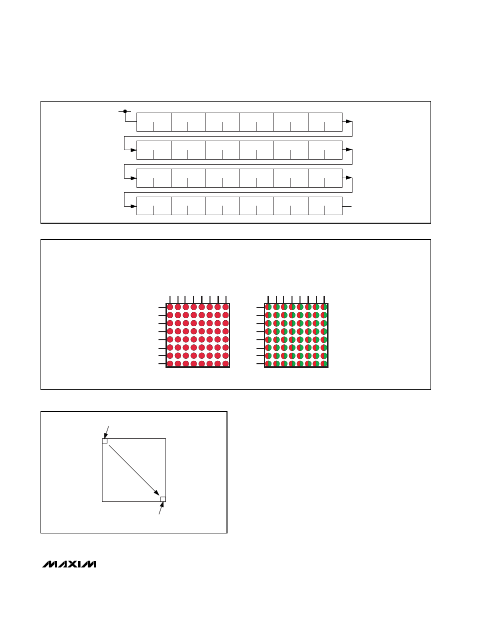
Figure 2. RGY 1-Bit-per-Pixel 48-Pixel x 32-Pixel Display Example
COLUMN 1
COLUMN 2
COLUMN 3
COLUMN 4
COLUMN 5
COLUMN 6
COLUMN 7
COLUMN 8
ROW 1
ROW 2
ROW 3
ROW 4
ROW 5
ROW 6
ROW 7
ROW 8
MONOCOLOR
COLUMN 1 (RED)
ROW 1
ROW 2
ROW 3
ROW 4
ROW 5
ROW 6
ROW 7
ROW 8
RGY
COLUMN 9 (GREEN)
Figure 3. 8 x 8 Matrix Pin Assignment
FIRST DISPLAY PIXEL
MAPS TO FIRST PLANE
LAST DISPLAY PIXEL
MAPS TO LAST PLANE
MEMORY LOCATION
Figure 4. How Plane Memory Across Multiple
MAX6960–MAX6963 Maps to Display Pixels