Rainbow Electronics MAX6963 User Manual
Page 28
MAX6960–MAX6963
the supply bus at least every several MAX6960s. Each
MAX6960 draws a peak current of either 40mA x 16
segments = 640mA (current setting = high) or 20mA x
16 segments = 320mA (current setting = low), regard-
less of the PWM plane and pixel intensity settings. If
ripple sync and/or mux flip are enabled, then the timing
of these peak currents is desynchronized between dri-
vers, providing an easier load to the power supply. For
all but the smallest display panels, it is necessary to
use 2oz copper boards to minimize the voltage drops
across the supply planes with the high currents that are
required. Set the supply voltage to 3.6V at the panel
supply input to allow the most margin for on-board sup-
ply voltage drops. For the TQFN package, connect the
exposed pad to GND.
RST
Input
After power-up, each MAX6960 uses the 3-wire inter-
face to determine its driver address within the other
interconnected MAX6960s. This process cannot take
place until all MAX6960s have powered up. In many
systems, the MAX6960s are operated from different
regulated supplies with different power-up delays. Hold
RST of every interconnected MAX6960 low until 50ms
after the last MAX6960 has powered up.
RST must be
driven by a CMOS logic output supplied by V+. A
supervisor such as the MAX6821x526, which has an
adjustable power-up reset delay is a good choice.
Package Dissipation
Typical full-power (all segments on) device power dissi-
pation is 671mW (V+ = 3.3V, V
LED
= 2.3V, I
LED
=
40mA, 254/256 full intensity). Consider the effect of one
or more shorted display LEDs in planning dissipation
handling. The MAX6960 remains under the 1023mW
MQFP package dissipation limit at +70°C with V+ =
3.6V and V
LED
= 2.1V. The TQFN package is preferred
for 40mA segment current applications because the
2.16W package dissipation limit easily handles worst-
case applications including multiple shorted LEDs.
4-Wire Serially Interfaced
8 x 8 Matrix Graphic LED Drivers
28
______________________________________________________________________________________
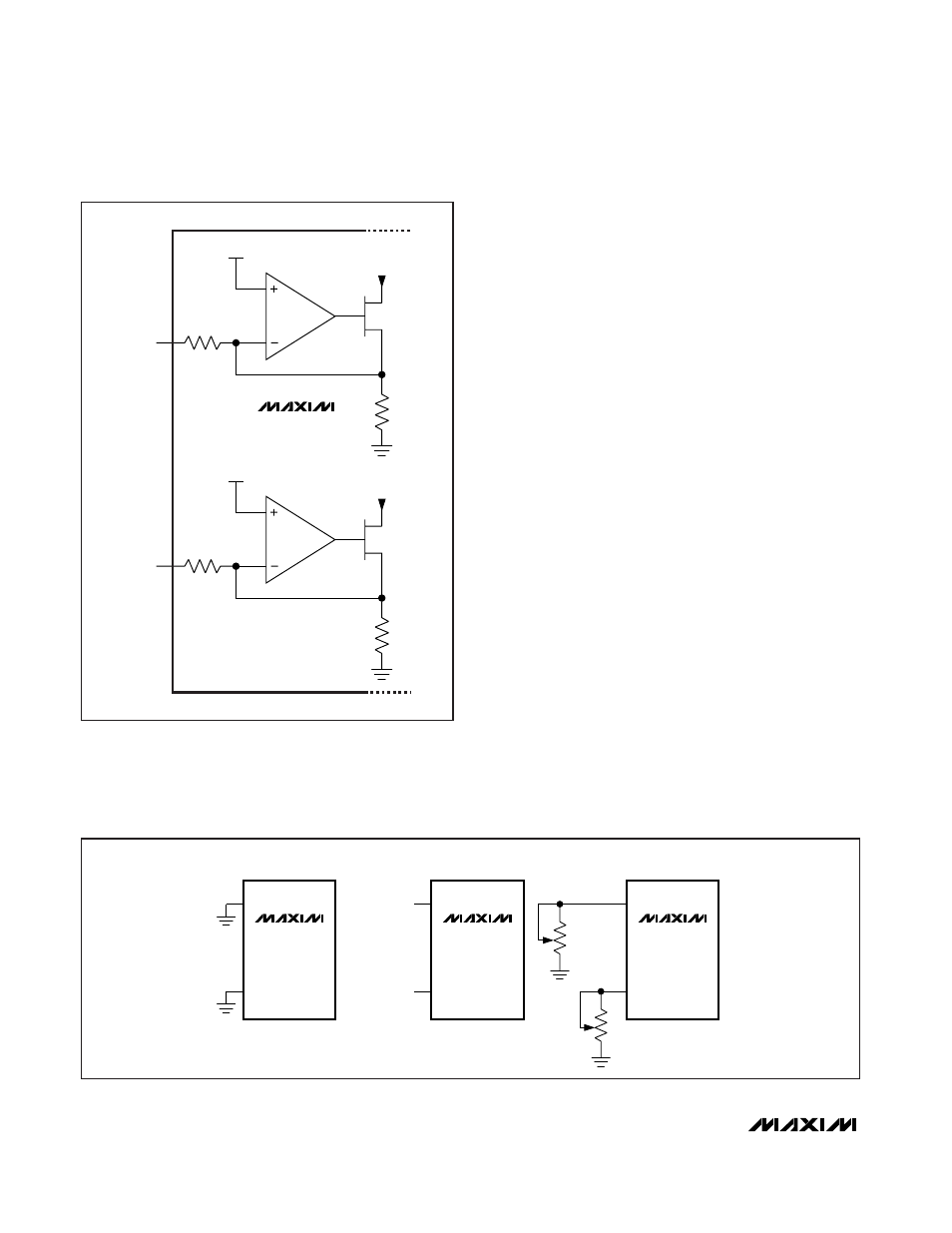
V
REF
TO RED
LED DRIVERS
R
INT
R
INT
RISET0
42
V
REF
TO GREEN
LED DRIVERS
R
INT
R
INT
RISET1
43
MAX6960
MAX6961
MAX6962
MAX6963
Figure 13. RISET0 and RISET1 Internal Architecture
MAX6960–
MAX6963
MAX6960–
MAX6963
MAX6960–
MAX6963
42
43
RISET0
RISET1
42
43
RISET0
RISET1
42
43
RISET0
RISET1
NO CONNECTION
NO CONNECTION
R0
R1
SETTING LED CURRENT
TO 40mA
ADJUSTABLE LED CURRENT
20mA
SETTING LED CURRENT
TO 20mA
Figure 14. RISET0 and RISET1 Pin Connections