Quick-start guide, Table 1. levels of functionality – Rainbow Electronics MAX6963 User Manual
Page 6
MAX6960–MAX6963
4-Wire Serially Interfaced
8 x 8 Matrix Graphic LED Drivers
6
_______________________________________________________________________________________
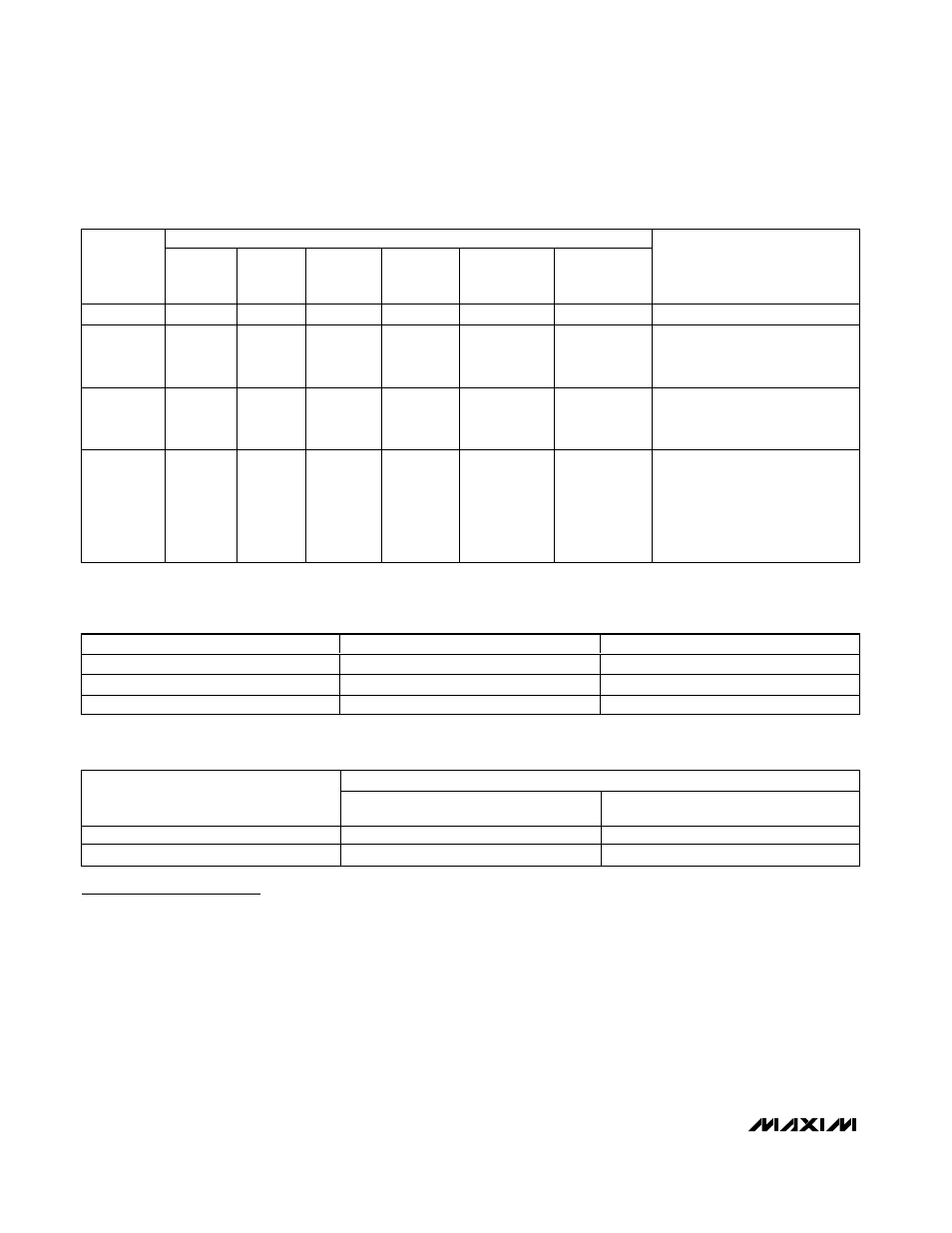
Quick-Start Guide
Selecting the Appropriate Driver
The MAX6960–MAX6963 matrix LED drivers are avail-
able in four versions, with different levels of functionality
(Table 1). The two-part ID bits in the fault and device ID
register (Table 32) identify the driver type to the inter-
face software. The ID bits may be of use if the same
panel software is used to drive more than one type of
display panel, because the software can automatically
detect the panel type.
This data sheet uses the generic name MAX6960 to
refer to the family of four parts MAX6960 through
MAX6963, unless there is a specific difference to
discuss.
The purpose of this quick-start guide is to provide an
overview of the capabilities of the MAX6960 so that the
driver can be easily evaluated for a particular applica-
tion, without fighting through a complex data sheet.
Terminology
• Pixel: One “point” on a display. Comprises one LED
for a monocolor display, two LEDs for an RGY dis-
play, and three LEDs for an RGB display.
• Monocolor: Display has only one color, typically red
for low-cost signs or orange for traffic signs. Varying
AVAILABLE FUNCTIONS
PART
RGB 2
BITS PER
PIXEL*
RGB
1 BIT PER
PIXEL*
RGY
2 BITS PER
PIXEL
RGY
1 BIT PER
PIXEL
MONOCOLOR
2 BITS PER
PIXEL
MONOCOLOR
1 BIT PER
PIXEL
REGISTER LIMITATIONS
MAX6960
√
√
√
√
√
√
None.
MAX6961
—
√
—
√
—
√
PI bit (bit D7) in global panel
configuration register is fixed at 0
(Table 22).
MAX6962
√
√
—
—
√
√
C bit (bit D6) in global panel
configuration register is fixed at 0
(Table 21).
MAX6963
—
√
—
—
—
√
C bit (bit D6) in global panel
configuration register is fixed at 0
(Table 21).
PI bit (bit D7) in global panel
configuration register is fixed at 0
(Table 22).
Table 1. Levels of Functionality
DISPLAY CONFIGURATION
MAXIMUM PIXEL COUNT
EXAMPLE MAXIMUM PANEL (PIXELS)
Monocolor
32,768
256 x 128
RGY
16,384
256 x 64
RGB
32,768 (3 buses required; see Figure 17)
128 x 85
Table 2. Maximum Display Matrix on a Single 4-Wire Interface
256 DRIVERS ON 4-WIRE INTERFACE, 50 FRAMES PER SECOND UPDATE RATE
DISPLAY-MEMORY-ACCESS METHOD
1-BIT-PER-PIXEL INTENSITY
CONTROL (Mbps)
2-BITS-PER-PIXEL INTENSITY
CONTROL (Mbps)
8-bit indirect display memory addressing
1.64
3.28
24-bit direct display memory addressing
4.92
9.83
Table 3. 4-Wire Interface Speed Requirements for Animation
*When operated per Figure 17.