Local 3-wire serial interface – Rainbow Electronics MAX6963 User Manual
Page 14
MAX6960–MAX6963
4-Wire Serially Interfaced
8 x 8 Matrix Graphic LED Drivers
14
______________________________________________________________________________________
observing the setup and hold times. Bit D15 is low,
indicating a write command.
For a 24-bit transmission:
Clock 24 bits of data into DIN, D23 first to D0 last,
observing the setup and hold times. Bit D23 is low,
indicating a write command.
4) Take
CS high (while CLK is still high after clocking
in the last data bit).
5) Take CLK low.
Reading Device Registers
Any register data within the MAX6960 may be read by
sending a logic-high to bit D15. The sequence is:
1) Take CLK low.
2) Take
CS low.
3) For a 16-bit transmission:
Clock 16 bits of data into DIN, D15 first to D0 last,
observing the setup and hold times. Bit D15 is high,
indicating a read command. Bits D7 to D0 are
dummy bits, and are discarded by the MAX6960.
For a 24-bit transmission: Clock 24 bits of data into
DIN, D23 first to D0 last, observing the setup and
hold times. Bit D23 is high, indicating a read com-
mand. Bits D7 to D0 are dummy bits, and are dis-
carded by the MAX6960.
4) Take
CS high (while CLK is still high after clocking
in the last data bit).
5) Take CLK low.
6) The selected MAX6960’s DOUT is enabled from tri-
state for read back.
7) Clock 8 bits of data from DOUT, D7 first to D0 last,
observing the setup and hold times.
8) Take CLK low after the final (8th) data bit.
The selected MAX6960’s DOUT returns to tri-state.
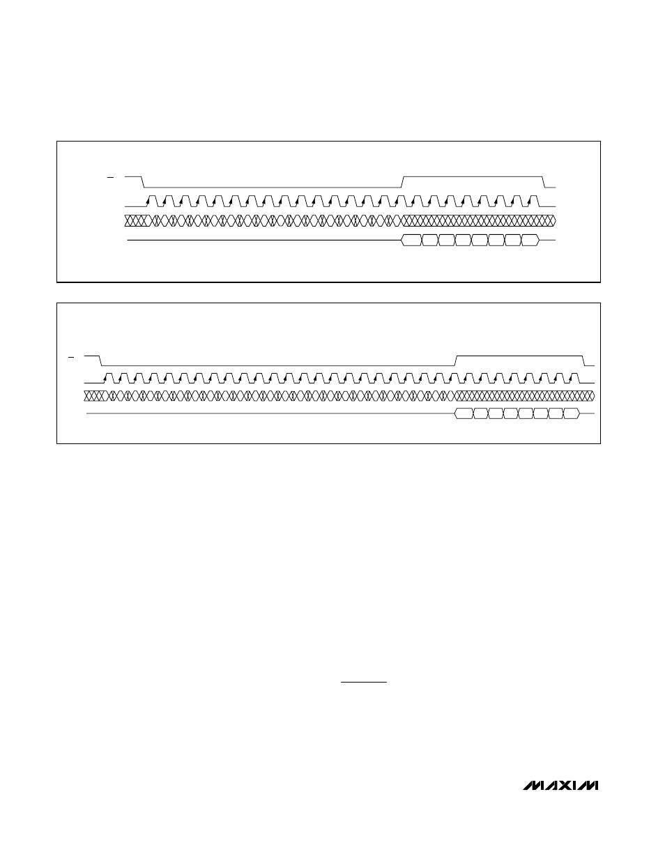
Figure 10 shows a read operation when 24 bits are
transmitted and 8 bits are read back.
Local 3-Wire Serial Interface
The MAX6960 uses a 3-wire interface to bus together
up to 256 MAX6960s. The 3-wire bus enables each
device to calculate its own unique driver address
(0 to 255), and reconfigure its display memory. The
ADDOUT output also provides an interrupt at every
page change, when the plane counter is configured to
automatic (Table 30).
D7
D6
D5
D4
D3
D2
D1
CS
CLK
DIN
DOUT
D15
= 1
TRI-STATE
D14
D13
D12
D11
D10
D9
D8
D0
.
D7
D6
D5
D4
D3
D2
D1
D0
Figure 9. 16-Bit Read from the MAX6960–MAX6963
D22
D21
D20
D19
D18
D7
D6
D5
D4
D3
D2
D1
CS
CLK
DIN
DOUT
D23
= 1
TRI-STATE
D14
D13
D12
D11
D10
D9
D8
D16
D15
D17
D0
.
D7
D6
D5
D4
D3
D2
D1
D0
Figure 10. 24-Bit Read from the MAX6960–MAX6963