Table 23. frame modulation with pixel intensity, Table 24. pixel intensity scale register format – Rainbow Electronics MAX6963 User Manual
Page 22
MAX6960–MAX6963
4-Wire Serially Interfaced
8 x 8 Matrix Graphic LED Drivers
22
______________________________________________________________________________________
REGISTER DATA
REGISTER
ADDRESS
CODE (HEX)
D7
D6
D5
D4
D3
D2
D1
D0
Display panel is built with monocolor or RGB
digits (permanently set this way for MAX6962 and
MAX6963)
0x0D
PI
0
F
R
DP1
DP0
IP
S
Display panel is built with RGY digits
0x0D
PI
1
F
R
DP1
DP0
IP
S
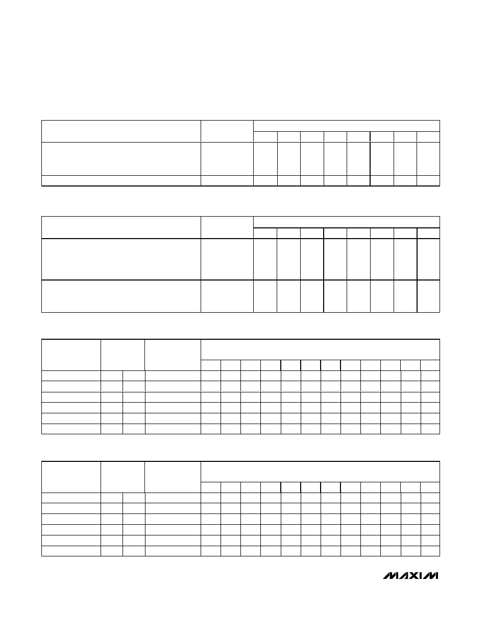
Table 21. Global Panel Configuration—Color Control (C Data Bit D6) Format
REGISTER DATA
REGISTER
ADDRESS
CODE (HEX)
D7
D6
D5
D4
D3
D2
D1
D0
Four display memory planes (0, 1, 2, 3) available;
pixel level-intensity control is 1 bit per pixel per
color (on/off) (permanently set this way for
MAX6961 and MAX6963)
0x0D
0
C
F
R
DP1
DP0
IP
S
Two display memory planes (0, 1) available;
pixel level-intensity control is 2 bits per pixel per
color (4 levels)
0x0D
1
C
F
R
DP1
DP0
IP
S
Table 22. Global Panel Configuration—Planes/Intensity Control (PI Data Bit D7) Format
PATTERN OF MULTIPLEX CYCLES
FOR WHICH A PIXEL IS ENABLED
PIXEL
GRADUATION
PIXEL
DATA
PIXEL
INTENSITY
SETTING
0
1
2
3
4
5
6
7
8
9
10
11
Both
1
1
Full
1
1
1
1
1
1
1
1
1
1
1
1
Arithmetic
1
0
2/3
1
0
1
1
0
1
1
0
1
1
0
1
Geometric
1
0
1/2
1
0
1
0
1
0
1
0
1
0
1
0
Arithmetic
0
1
1/3
0
1
0
0
1
0
0
1
0
0
1
0
Geometric
0
1
1/4
0
1
0
0
0
1
0
0
0
1
0
0
Both
0
0
Off
0
0
0
0
0
0
0
0
0
0
0
0
Table 23. Frame Modulation with Pixel Intensity
PATTERN OF MULTIPLEX CYCLES
FOR WHICH A PIXEL IS ENABLED
PIXEL
GRADUATION
PIXEL
DATA
PIXEL
INTENSITY
SETTING
0
1
2
3
4
5
6
7
8
9
10
11
Both
1
1
Full
1
1
1
1
1
1
1
1
1
1
1
1
Arithmetic
1
0
2/3
1
0
1
1
0
1
1
0
1
1
0
1
Geometric
1
0
1/2
1
0
1
0
1
0
1
0
1
0
1
0
Arithmetic
0
1
1/3
0
1
0
0
1
0
0
1
0
0
1
0
Geometric
0
1
1/4
0
1
0
0
0
1
0
0
0
1
0
0
Both
0
0
Off
0
0
0
0
0
0
0
0
0
0
0
0
Table 24. Pixel Intensity Scale Register Format