Detailed description – Rainbow Electronics MAX6963 User Manual
Page 8
MAX6960–MAX6963
4-Wire Serially Interfaced
8 x 8 Matrix Graphic LED Drivers
8
_______________________________________________________________________________________
Software Control
The hardware features are designed to simplify the
software interface and eliminate software timing depen-
dencies:
• Two or four planes of display memory are stored,
allowing images to be preloaded into the MAX6960–
MAX6963 frame memory.
• Animation timing is built in, sequencing through the
two or four planes automatically. System software
has to update the upcoming plane(s) with new data
ahead of time, but do not be concerned about exact
timing. The frame rate is adjustable to as fast as 63
frames a second for animations, or to as slow as one
frame change every 63s for advertising sequencing.
• Multiple MAX6960s interconnect and share display
memory so that the software “sees” the display as
memory-mapped planes of contiguous RAM.
• Global commands that need to be received and
acted on by every MAX6960 in a panel do just that,
with one write.
Hardware Design
A MAX6960 normally drives an 8 x 16 LED matrix, com-
prising 8 cathode rows and 16 anode columns, or
8 anode rows and 16 cathode columns with external
drivers.
The MAX6960 standard wiring connection to either two
monocolor 8 x 8 digits, or to a single RGY 8 x 8 digit is
shown in Table 4. Figure 3 shows the display pin naming.
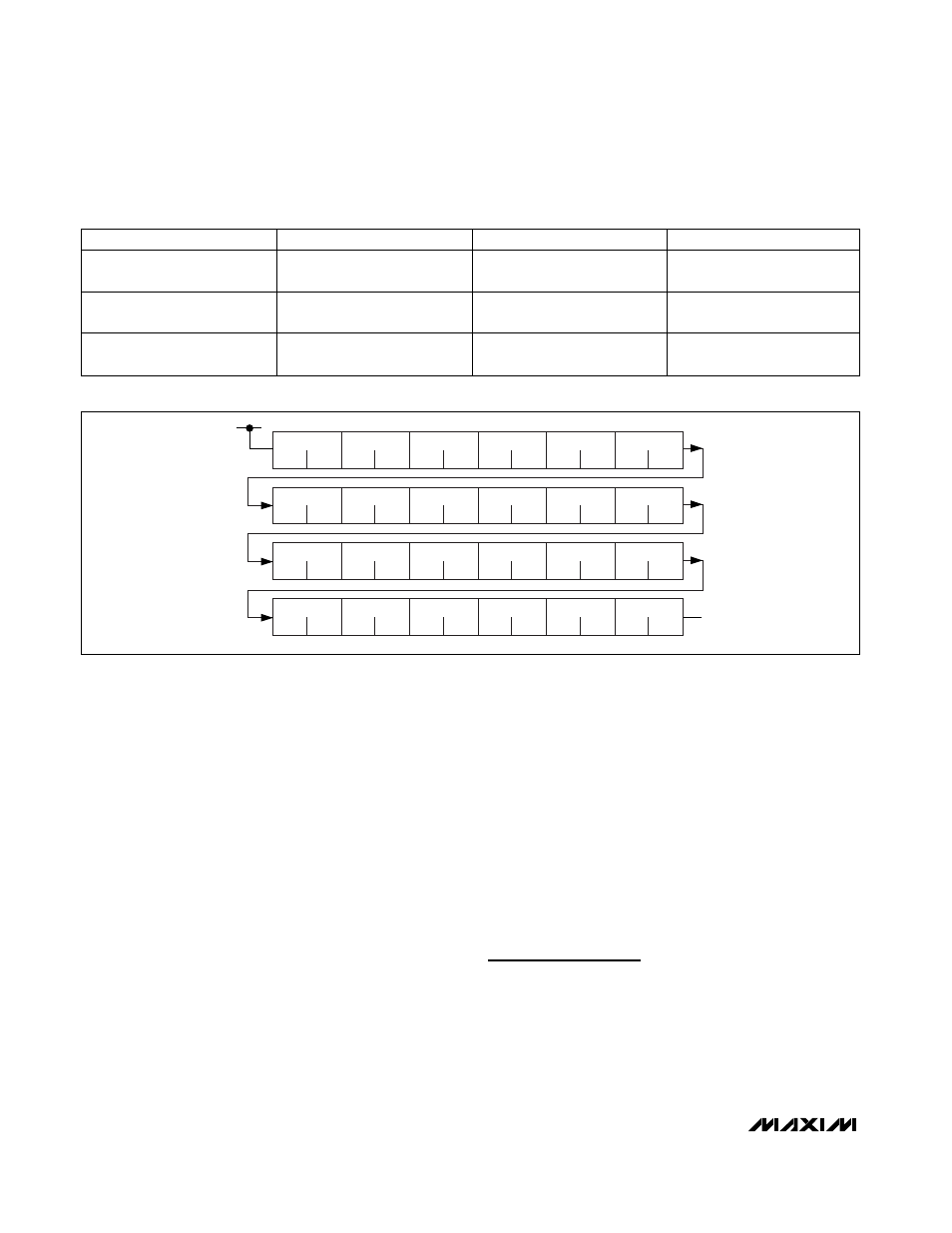
Figures 1 and 2 show example displays with the
MAX6960 drivers connecting to monocolor and RGY pan-
els. Figure 4 shows how the display memory maps to the
physical pixels on the display panel, provided that the
MAX6960 drivers are interconnected correctly in a raster-
like manner from top left of the panel to bottom right.
Detailed Description
Overview
The MAX6960 is an LED display driver capable of driving
either two monocolor 8 x 8 cathode-row matrix digits, or a
single RGY 8 x 8 cathode-row matrix digit. The architec-
ture of the driver is designed to allow a large graphic
DRIVER PINS ROW1–ROW8
DRIVER PINS COL1–COL8
DRIVER PINS COL9–COL16
Monocolor digit 0 (red*)
Digit 0 (red*) rows (cathodes)
R1 to R8
Digit 0 columns (anodes) C1 to
C8
—
Monocolor digit 1 (green*)
Digit 1 (green*) rows
(cathodes) R1 to R8
—
Digit 1 columns (anodes) C1 to
C8
RGY red/green
Red/green rows (cathodes) R1
to R8
Red columns (anodes) C1 to
C8
Green columns (anodes) C1 to
C8
Table 4. Standard Driver Connection to Monocolor and RGY 8 x 8 Displays
*Digit 0 of a monocolor display is called red, and digit 1 is called green in the data sheet.
RED
DRIVER0
RED
RED
DRIVER1
RED
RED
DRIVER2
RED
RED
DRIVER3
RED
RED
DRIVER4
RED
RED
DRIVER5
RED
RED
DRIVER6
RED
RED
DRIVER7
RED
RED
DRIVER8
RED
RED
DRIVER9
RED
RED
DRIVER10
RED
RED
DRIVER11
RED
RED
DRIVER12
RED
RED
DRIVER13
RED
RED
DRIVER14
RED
RED
DRIVER15
RED
RED
DRIVER16
RED
RED
DRIVER17
RED
RED
DRIVER18
RED
RED
DRIVER19
RED
RED
DRIVER20
RED
RED
DRIVER21
RED
RED
DRIVER22
RED
RED
DRIVER23
RED
Figure 1. Monocolor 1-Bit-per-Pixel, 96-Pixel x 32-Pixel Display Example