Rainbow Electronics MAX8760 User Manual
Page 29
MAX8760
Dual-Phase, Quick-PWM Controller for AMD
Mobile Turion 64 CPU Core Power Supplies
______________________________________________________________________________________
29
Low-Power Pulse Skipping
During pulse-skipping override mode (SKIP = REF or
GND, Table 7), the multiphase quick-PWM controllers
use an automatic pulse-skipping control scheme. When
SKIP is pulled low, the controller uses the automatic
pulse-skipping control scheme, overriding forced-PWM
operation, and blanks the upper VROK threshold.
SKIP is a three-level logic input—GND, REF, or high.
This input is intended to be driven by a dedicated
open-drain output with the pullup resistor connected
either to REF (or a resistive divider from V
CC
) or to a
logic-level high-bias supply (3.3V or greater).
When driven to GND, the multiphase Quick-PWM
controller disables the secondary phase (DLS = PGND
and DHS = LXS) and the primary phase uses the auto-
matic pulse-skipping control scheme. When pulled up
to REF, the controller keeps both phases active and
uses the automatic pulse-skipping control scheme—
alternating between the primary and secondary phases
with each cycle.
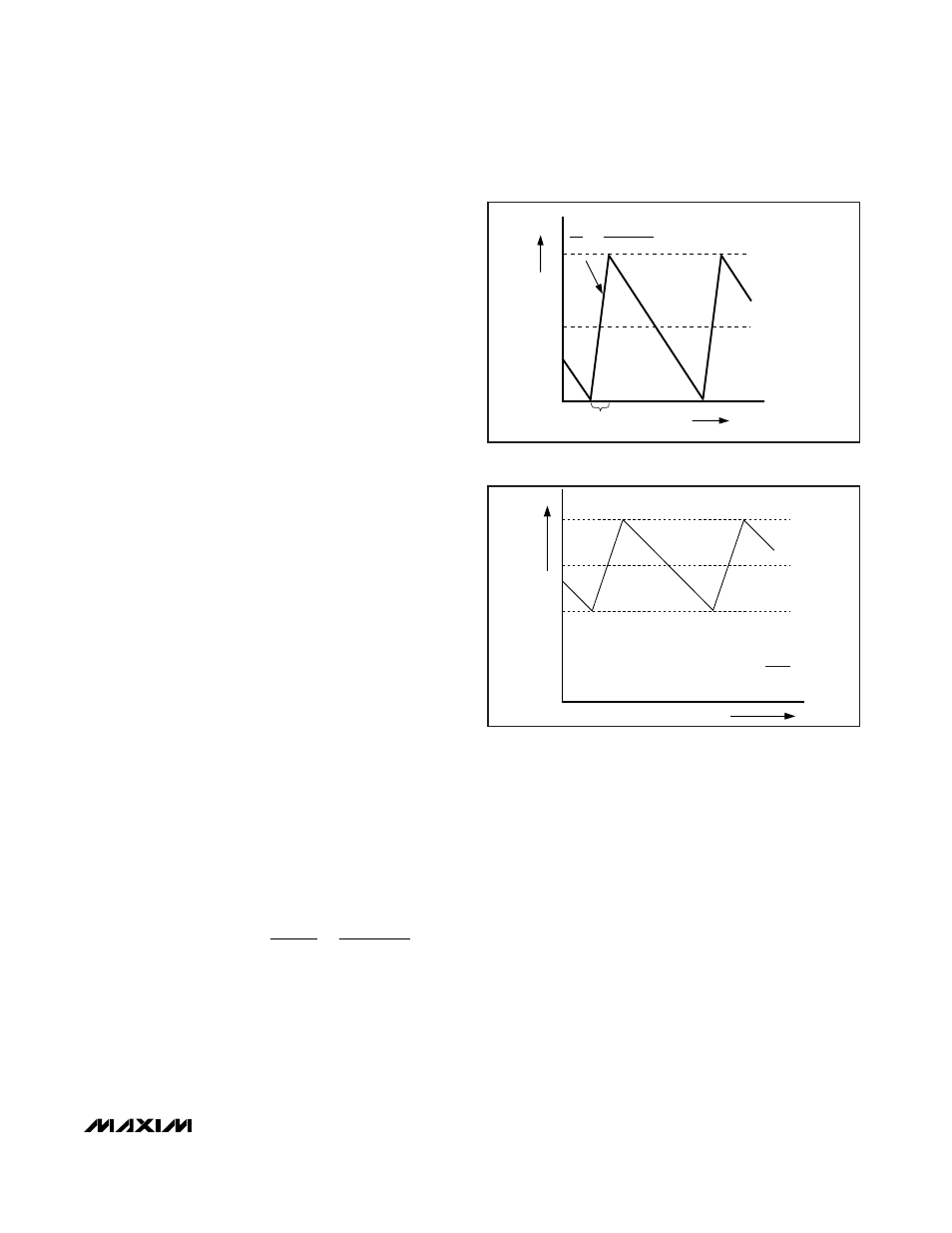
Automatic Pulse-Skipping Switchover
In skip mode (SKIP = REF or GND), an inherent automatic
switchover to PFM takes place at light loads (Figure 7). A
comparator that truncates the low-side switch on-time at
the inductor current’s zero crossing affects this switch-
over. The zero-crossing comparator senses the inductor
current across the current-sense resistors. Once V
C
_
P
-
V
C
_
N
drops below the zero-crossing comparator thresh-
old (see the Electrical Characteristics table), the com-
parator forces DL low (Figure 5). This mechanism causes
the threshold between pulse-skipping PFM and nonskip-
ping PWM operation to coincide with the boundary
between continuous and discontinuous inductor-current
operation. The PFM/PWM crossover occurs when the
load current of each phase is equal to 1/2 the peak-to-
peak ripple current, which is a function of the inductor
value (Figure 7). For a battery input range of 7V to 20V,
this threshold is relatively constant, with only a minor
dependence on the input voltage due to the typically low
duty cycles. The total load current at the PFM/PWM
crossover threshold (I
LOAD(SKIP)
) is approximately:
where
η
TOTAL
is the number of active phases, and K is
the on-time scale factor (Table 6).
The switching waveforms may appear noisy and asyn-
chronous when light loading activates pulse-skipping
operation, but this is a normal operating condition that
results in high light-load efficiency. Varying the inductor
value makes trade-offs between PFM noise and light-load
efficiency. Generally, low inductor values produce a
broader efficiency vs. load curve, while higher values
result in higher full-load efficiency (assuming that the coil
resistance remains fixed) and less output voltage ripple.
Penalties for using higher inductor values include larger
physical size and degraded load-transient response,
especially at low input voltage levels.
Current-Limit Circuit
The current-limit circuit employs a unique “valley” current-
sensing algorithm that uses current-sense resistors
between the current-sense inputs (C_P to C_N) as the cur-
rent-sensing elements. If the current-sense signal of the
selected phase is above the current-limit threshold, the
PWM controller does not initiate a new cycle (Figure 8)
until the inductor current of the selected phase drops
below the valley current-limit threshold. When either phase
trips the current limit, both phases are effectively current
limited since the interleaved controller does not initiate a
cycle with either phase.
I
K
LOAD SKIP
TOTAL
(
)
=
η
V
L
V
- V
V
OUT
IN
OUT
IN
INDUCTOR CURRENT
I
LOAD
= I
PEAK
/2
ON-TIME
0
TIME
I
PEAK
L
V
BATT
- V
OUT
∆i
∆t
=
Figure 7. Pulse-Skipping/Discontinuous Crossover Point
INDUCTOR CURRENT
I
LIMIT(VALLEY)
= I
LOAD(MAX)
2 - LIR
2
η
(
)
TIME
0
I
PEAK
I
LOAD
I
LIMIT
Figure 8. “Valley” Current-Limit Threshold Point