Table 2. component suppliers – Rainbow Electronics MAX8760 User Manual
Page 19
MAX8760
Dual-Phase, Quick-PWM Controller for AMD
Mobile Turion 64 CPU Core Power Supplies
______________________________________________________________________________________
19
Internal Multiplexers
The MAX8760 has a unique internal DAC input
multiplexer (MUXes) that selects one of three different
DAC code settings for different processor states
(Figure 3). On startup, the MAX8760 selects the DAC
code from the D0–D5 (SUS = GND) or S0, S1 (SUS = REF
or high) input decoders.
DAC Inputs (D0–D5)
During normal forced-PWM operation (SUS = GND), the
digital-to-analog converter (DAC) programs the output
voltage using the D0–D5 inputs. Do not leave D0–D5
unconnected. D0–D5 can be changed while the
MAX8760 is active, initiating a transition to a new output
voltage level. Change D0–D5 together, avoiding greater
than 1µs skew between bits. Otherwise, incorrect DAC
readings can cause a partial transition to the wrong volt-
age level followed by the intended transition to the correct
voltage level, lengthening the overall transition time. The
available DAC codes and resulting output voltages are
compatible with AMD K9 voltage specifications (Table 4).
MANUFACTURER
PHONE
WEBSITE
BI Technologies
714-447-2345 (USA)
www.bitechnologies.com
Central Semiconductor
631-435-1110 (USA)
www.centralsemi.com
Coilcraft
800-322-2645 (USA)
www.coilcraft.com
Coiltronics
561-752-5000 (USA)
www.coiltronics.com
Fairchild Semiconductor
888-522-5372 (USA)
www.fairchildsemi.com
International Rectifier
310-322-3331 (USA)
www.irf.com
Kemet
408-986-0424 (USA)
www.kemet.com
Panasonic
847-468-5624 (USA)
www.panasonic.com
Sanyo
65-6281-3226 (Singapore)
www.secc.co.jp
Siliconix (Vishay)
203-268-6261 (USA)
www.vishay.com
Sumida
408-982-9660 (USA)
www.sumida.com
Taiyo Yuden
03-3667-3408 (Japan)
408-573-4150 (USA)
www.t-yuden.com
TDK
847-803-6100 (USA)
81-3-5201-7241 (Japan)
www.component.tdk.com
TOKO
858-675-8013 (USA)
www.tokoam.com
Table 2. Component Suppliers
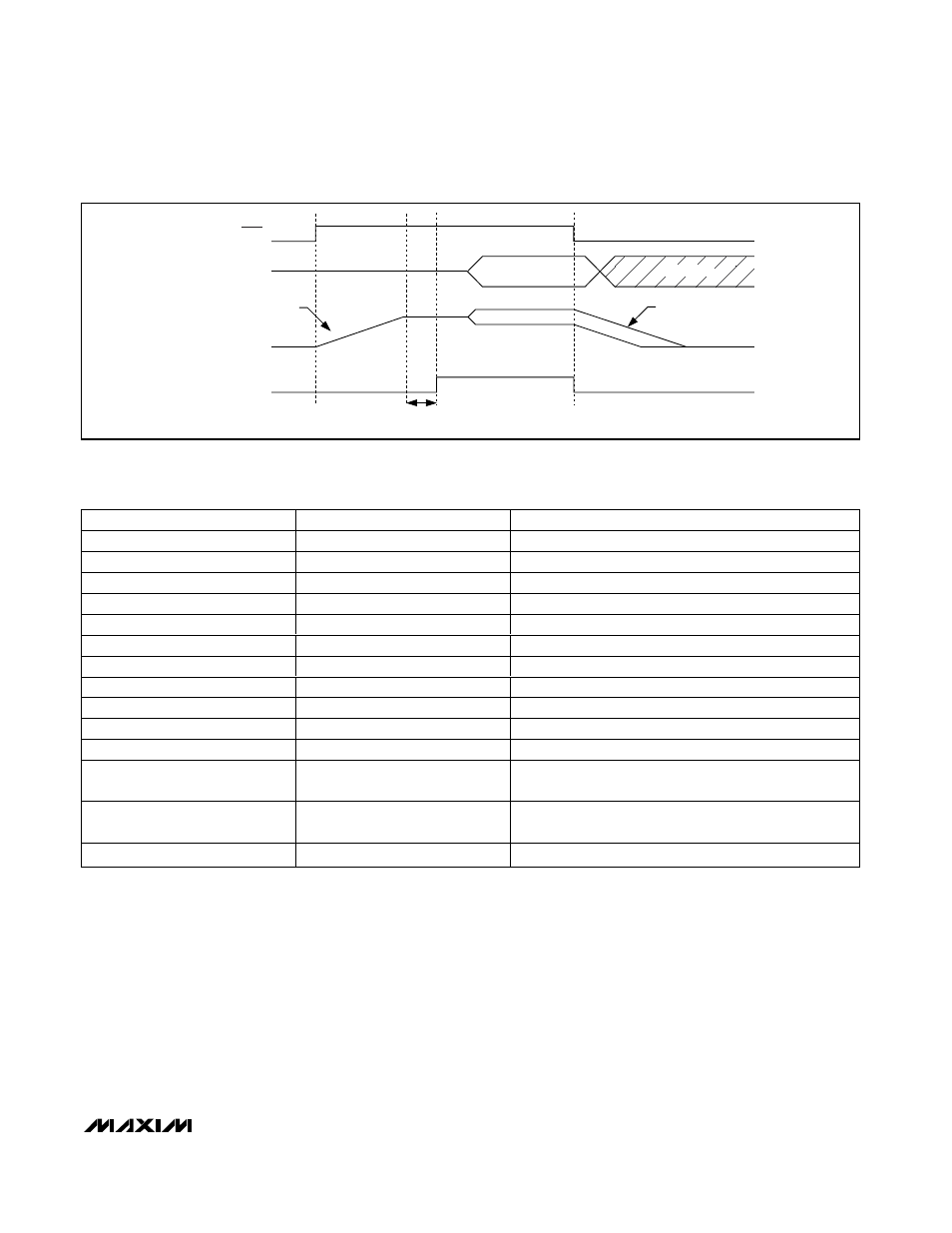
VID (D0–D5)
SHDN
V
CORE
t
VROK(START)
5ms (TYP)
SOFT-SHUTDOWN
1 LSB PER 4 R
TIME
CYCLES
SOFT-START
1 LSB PER 4 R
TIME
CYCLES
VROK
DO NOT CARE
Figure 2. Power-Up and Shutdown Sequence Timing Diagram