Rainbow Electronics MAX8760 User Manual
Page 22
MAX8760
Dual-Phase, Quick-PWM Controller for AMD
Mobile Turion 64 CPU Core Power Supplies
22
______________________________________________________________________________________
Fault Protection
Output Overvoltage Protection
The OVP circuit is designed to protect the CPU against a
shorted high-side MOSFET by drawing high current and
blowing the battery fuse. The MAX8760 continuously
monitors the output for an overvoltage fault. The controller
detects an OVP fault if the output voltage exceeds the
fixed 2.0V (typ) threshold. When the OVP circuit detects
an overvoltage fault, it immediately sets the fault latch,
turns off the high-side MOSFETs, and forces DL high.
This action discharges the output filter capacitor and
forces the output to ground. If the condition that caused
the overvoltage (such as a shorted high-side MOSFET)
persists, the battery fuse blows. The controller remains
shut down until the fault latch is cleared by toggling
SHDN or cycling the V
CC
power supply below 1V.
The OVP is disabled when the controller is in the no-fault
test mode (see the No-Fault Test Mode section).
Output Undervoltage Shutdown
The output UVP function is similar to foldback current
limiting, but employs a timer rather than a variable current
limit. If the MAX8760 output voltage is under 70% of the
nominal value, the controller activates the shutdown
sequence and sets the fault latch.
Once the controller ramps down to the 0V DAC code
setting, it forces the DL_ low-side gate driver high and
pulls the DH_ high-side gate driver low. Toggle SHDN
or cycle the V
CC
power supply below 1V to clear the
fault latch and reactivate the controller. UVP is ignored
during output voltage transitions and remains blanked
for an additional 24 clock cycles after the controller
reaches the final DAC code value.
UVP can be disabled through the no-fault test mode
(see the No-Fault Test Mode section).
Thermal-Fault Protection
The MAX8760 features a thermal-fault protection circuit.
When the junction temperature rises above +160°C, a
thermal sensor activates the fault latch and the soft-
shutdown sequence. Once the controller ramps down
to the 0V DAC code setting, it forces the DL_ low-side
gate driver high, and pulls the DH_ high-side gate
driver low. Toggle SHDN or cycle the V
CC
power supply
below 1V to clear the fault latch and reactivate the con-
troller after the junction temperature cools by 15°C.
Thermal shutdown can be disabled through the
no-fault test mode (see the No-Fault Test Mode section).
No-Fault Test Mode
The latched-fault protection features and overlap mode
can complicate the process of debugging prototype
breadboards since there are (at most) a few milliseconds
in which to determine what went wrong. Therefore, a no-
fault test mode is provided to disable the fault protection
(overvoltage protection, undervoltage protection, and
thermal shutdown) and overlap mode. Additionally, the
test mode clears the fault latch if it has been set. The no-
fault test mode is entered by forcing 12V to 15V on SHDN.
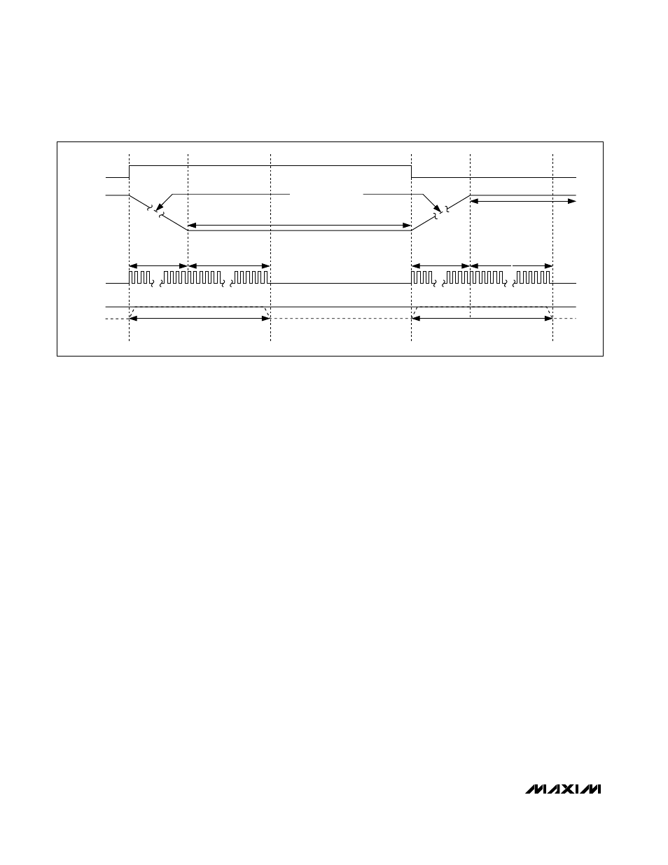
SUS
V
DAC
TIME
CLOCK
VROK
VROK BLANKING
VROK BLANKING
OUTPUT SET BY SUS AND S0, S1
OUTPUT SET BY D0–D4
1 LSB PER R
TIME
CYCLE
t
SLEW
t
BLANK
= 24 CLKS
t
SLEW
t
BLANK
= 24 CLKS
Figure 4. Suspend Transition