Rainbow Electronics MAX8760 User Manual
Page 21
MAX8760
Dual-Phase, Quick-PWM Controller for AMD
Mobile Turion 64 CPU Core Power Supplies
______________________________________________________________________________________
21
The slew-rate controller transitions the output voltage in
12.5mV steps during soft-start, soft-shutdown, and sus-
pend-mode transitions. The total time for a transition
depends on R
TIME
, the voltage difference, and the
accuracy of the MAX8760’s slew-rate clock, and is not
dependent on the total output capacitance. The greater
the output capacitance, the higher the surge current
required for the transition. The MAX8760 automatically
controls the current to the minimum level required to
complete the transition in the calculated time, as long
as the surge current is less than the current limit set by
ILIM. The transition time is given by:
where f
SLEW
= 500kHz
✕
30k
Ω / R
TIME
, V
OLD
is the
original DAC setting, V
NEW
is the new DAC setting, and
V
LSB
= 12.5mV is the DAC’s smallest voltage incre-
ment. The additional two clock cycles on the falling
edge time are due to internal synchronization delays.
See TIME Frequency Accuracy in the Electrical
Characteristics table for f
SLEW
limits.
The practical range of R
TIME
is 15k
Ω to 150kΩ, corre-
sponding to 1.0µs to 10µs per 12.5mV step. Although
the DAC takes discrete steps, the output filter makes
the transitions relatively smooth. The average inductor
current required to make an output voltage transition is:
I
C
V
f
L
OUT
LSB
SLEW
≅
Ч
Ч
t
f
V
V
V
for V
ri
g
t
f
V
V
V
for V
falling
SLEW
SLEW
OLD
NEW
LSB
OUT
SLEW
SLEW
OLD
NEW
LSB
OUT
≈
≈
+
−
−
1
1
2
sin
S0
S1
S0, S1
DECODER
IN
SEL
SUS
SUSPEND
MUX
OUT
1
0
SEL
DAC
1.0V
2.5V
SUS 3-LEVEL
DECODER
OUT
D0–D5
DECODER
OUT
IN
D3
D4
D1
D2
D0
D5
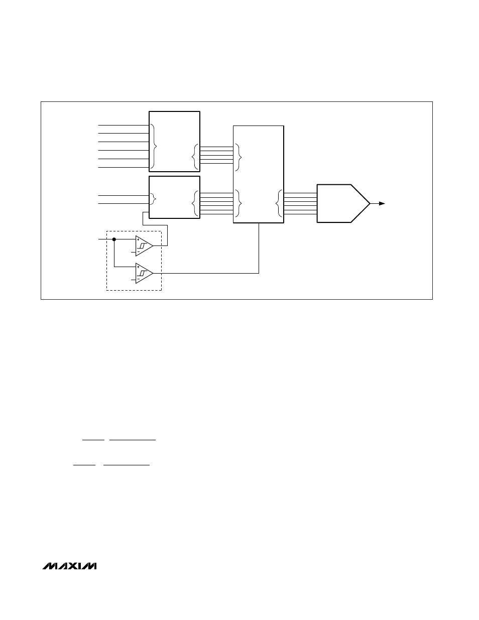
Figure 3. Internal Multiplexers Functional Diagram