Rainbow Electronics MAX8760 User Manual
Page 17
MAX8760
Dual-Phase, Quick-PWM Controller for AMD
Mobile Turion 64 CPU Core Power Supplies
______________________________________________________________________________________
17
For the MAX8760, the slew-rate controller ramps up the
output voltage in 12.5mV increments to the proper oper-
ating voltage (see Tables 3 and 4) set by either D0–D5
(SUS = GND) or S0, S1 (SUS = REF or high). The ramp
rate is set with the R
TIME
resistor (see the Output Voltage
Transition Timing section).
The ramp rate is 1/4 the rate set by the R
TIME
resistor
(see the Output Voltage Transition Timing section). The
controller pulls VROK low until at least 3ms after the
MAX8760 reaches the target DAC code.
Shutdown
When SHDN goes low, the MAX8760 enters low-power
shutdown mode. VROK is pulled low immediately, and
the output voltage ramps down to 0V in LSB increments
at 4 times the clock rate set by R
TIME
:
where f
SLEW
= 500kHz
✕
30k
Ω/R
TIME
, V
DAC
is the DAC
setting when the controller begins the shutdown
sequence, and V
LSB
= 12.5mV is the DAC’s smallest
voltage increment. Slowly discharging the output capac-
itors by slewing the output over a long period of time
(4/f
SLEW
) keeps the average negative inductor current
low (damped response), thereby eliminating the nega-
tive output voltage excursion that occurs when the con-
troller discharges the output quickly by permanently
turning on the low-side MOSFET (underdamped
response). This eliminates the need for the Schottky
diode normally connected between the output and
ground to clamp the negative output voltage excursion.
When the DAC reaches the 0V setting, DL_ goes high,
DH_ goes low, the reference turns off, and the supply
current drops to about 1µA. When a fault condition—out-
put undervoltage lockout, output overvoltage lockout, or
thermal shutdown—activates the shutdown sequence,
the controller sets the fault latch to prevent the controller
from restarting. To clear the fault latch and reactivate the
controller, toggle SHDN or cycle V
CC
power below 1V.
When SHDN goes high, the reference powers up. Once
the reference voltage exceeds its UVLO threshold, the
controller evaluates the DAC target and starts switching.
The slew-rate controller ramps up from 0V in LSB
increments to the currently selected output-voltage set-
ting at 1/4 the slew rate set by the R
TIME
resistor (see the
Power-Up Sequence section). There is no traditional soft-
start (variable current-limit) circuitry, so full output current
is available immediately.
t
f
V
V
SHDN
SLEW
DAC
LSB
≤
4
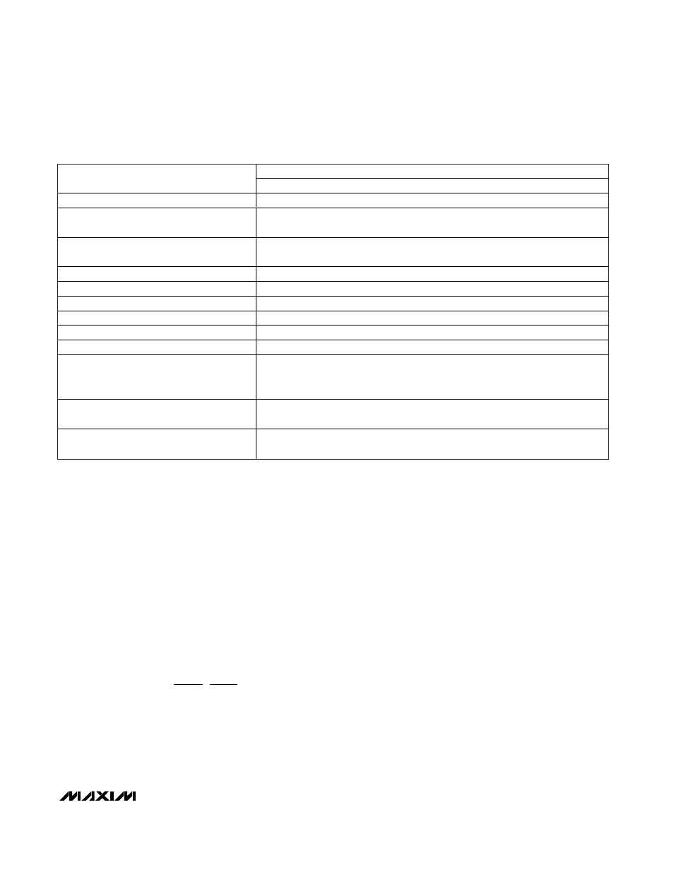
MAX8760 AMD MOBILE COMPONENTS
DESIGNATION
Circuit of Figure 1
Input Voltage Range
7V to 24V
VID Output Voltage
(D5–D0)
1.3V
(D5–D0 = 001010)
Suspend Voltage
(SUS, S0, S1)
Not used
(SUS = GND)
Maximum Load Current
30A
Number of Phases (
η
TOTAL
)
Two phases
Inductor (per Phase)
0.56µH Panasonic ETQP4LR56WFC
Switching Frequency
300kHz (TON = REF)
High-Side MOSFET (N
H
, per phase)
Siliconix (1) Si7886DP
Low-Side MOSFET (N
L
, per phase)
Siliconix (2) Si7356DP
Total Input Capacitance (C
IN
)
(4) 10µF, 25V
Taiyo Yuden TMK432BJ106KM or
TDK C4532X5R1E106M
Total Output Capacitance (C
OUT
)
(4) 330µF, 2.5V
Sanyo 2R5TPE330M9
Current-Sense Resistor (R
SENSE
, per Phase)
1m
Ω
Panasonic ERJM1WTJ1M0U
Table 1. Component Selection for Standard Multiphase Applications