Multiphase quick-pwm, Table 5. suspend mode dac codes – Rainbow Electronics MAX8760 User Manual
Page 24
MAX8760
Dual-Phase, Quick-PWM Controller for AMD
Mobile Turion 64 CPU Core Power Supplies
24
______________________________________________________________________________________
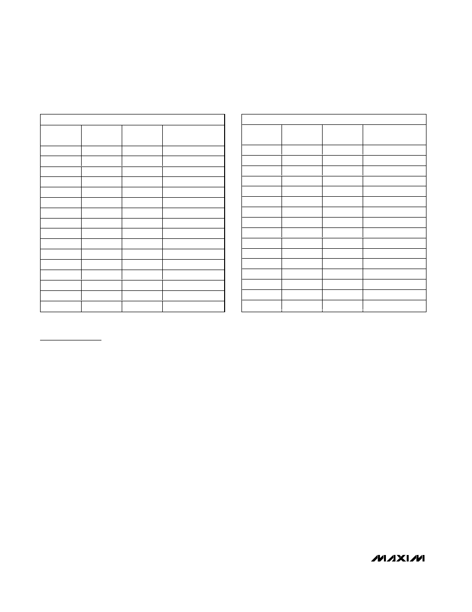
LOWER SUSPEND CODES
SUS
S1
S0
OUTPUT
VOLTAGE (V)
HIGH
GND
GND
0.800
HIGH
GND
REF
0.775
HIGH
GND
OPEN
0.750
HIGH
GND
V
CC
0.725
HIGH
REF
GND
0.700
HIGH
REF
REF
0.675
HIGH
REF
OPEN
0.650
HIGH
REF
V
CC
0.625
HIGH
OPEN
GND
0.600
HIGH
OPEN
REF
0.575
HIGH
OPEN
OPEN
0.550
HIGH
OPEN
V
CC
0.525
HIGH
V
CC
GND
0.500
HIGH
V
CC
REF
0.475
HIGH
V
CC
OPEN
0.450
HIGH
V
CC
V
CC
0.425
UPPER SUSPEND CODES
SUS
S1
S0
OUTPUT
VOLTAGE (V)
REF
GND
GND
1.200
REF
GND
REF
1.175
REF
GND
OPEN
1.150
REF
GND
V
CC
1.125
REF
REF
GND
1.100
REF
REF
REF
1.075
REF
REF
OPEN
1.050
REF
REF
V
CC
1.025
REF
OPEN
GND
1.000
REF
OPEN
REF
0.975
REF
OPEN
OPEN
0.950
REF
OPEN
V
CC
0.925
REF
V
CC
GND
0.900
REF
V
CC
REF
0.875
REF
V
CC
OPEN
0.850
REF
V
CC
V
CC
0.825
Table 5. Suspend Mode DAC Codes
*Connect the tri-level SUS input to a 2.7V or greater supply (3.3V or V
CC
) for an input logic level high.
Multiphase Quick-PWM
5V Bias Supply (V
CC
and V
DD
)
The Quick-PWM controller requires an external 5V bias
supply in addition to the battery. Typically, this 5V bias
supply is the notebook’s 95%-efficient 5V system sup-
ply. Keeping the bias supply external to the IC
improves efficiency and eliminates the cost associated
with the 5V linear regulator that would otherwise be
needed to supply the PWM circuit and gate drivers. If
stand-alone capability is needed, the 5V bias supply
can be generated with an external linear regulator.
The 5V bias supply must provide V
CC
(PWM controller)
and V
DD
(gate-drive power), so the maximum current
drawn is:
I
BIAS
= I
CC
+ f
SW
(Q
G(LOW)
+ Q
G(HIGH)
)
where I
CC
is provided in the Electrical Characteristics
table, f
SW
is the switching frequency, and Q
G(LOW)
and
Q
G(HIGH)
are the MOSFET data sheet’s total gate-charge
specification limits at V
GS
= 5V.
V+ and V
DD
can be connected together if the input
power source is a fixed 4.5V to 5.5V supply. If the 5V
bias supply is powered up prior to the battery supply,
the enable signal (SHDN going from low to high) must
be delayed until the battery voltage is present to ensure
startup.
Free-Running, Constant-On-Time PWM
Controller with Input Feed-Forward
The quick-PWM control architecture is a pseudofixed-fre-
quency, constant-on-time, current-mode regulator with
input voltage feed-forward (Figure 5). This architecture
relies on the output filter capacitor’s ESR to act as the
current-sense resistor, so the output ripple voltage pro-
vides the PWM ramp signal. The control algorithm is sim-
ple: the high-side switch on-time is determined solely by
a one-shot with a period inversely proportional to input
voltage, and directly proportional to output voltage or the
difference between the main and secondary inductor
currents (see the On-Time One-Shot (TON) section).
Another one-shot sets a minimum off-time. The on-time
one-shot triggers when the error comparator goes low,
the inductor current of the selected phase is below the
valley current-limit threshold, and the minimum off-time
one-shot times out. The controller maintains 180° out-of-
phase operation by alternately triggering the main and
secondary phases after the error comparator drops
below the output voltage set point.