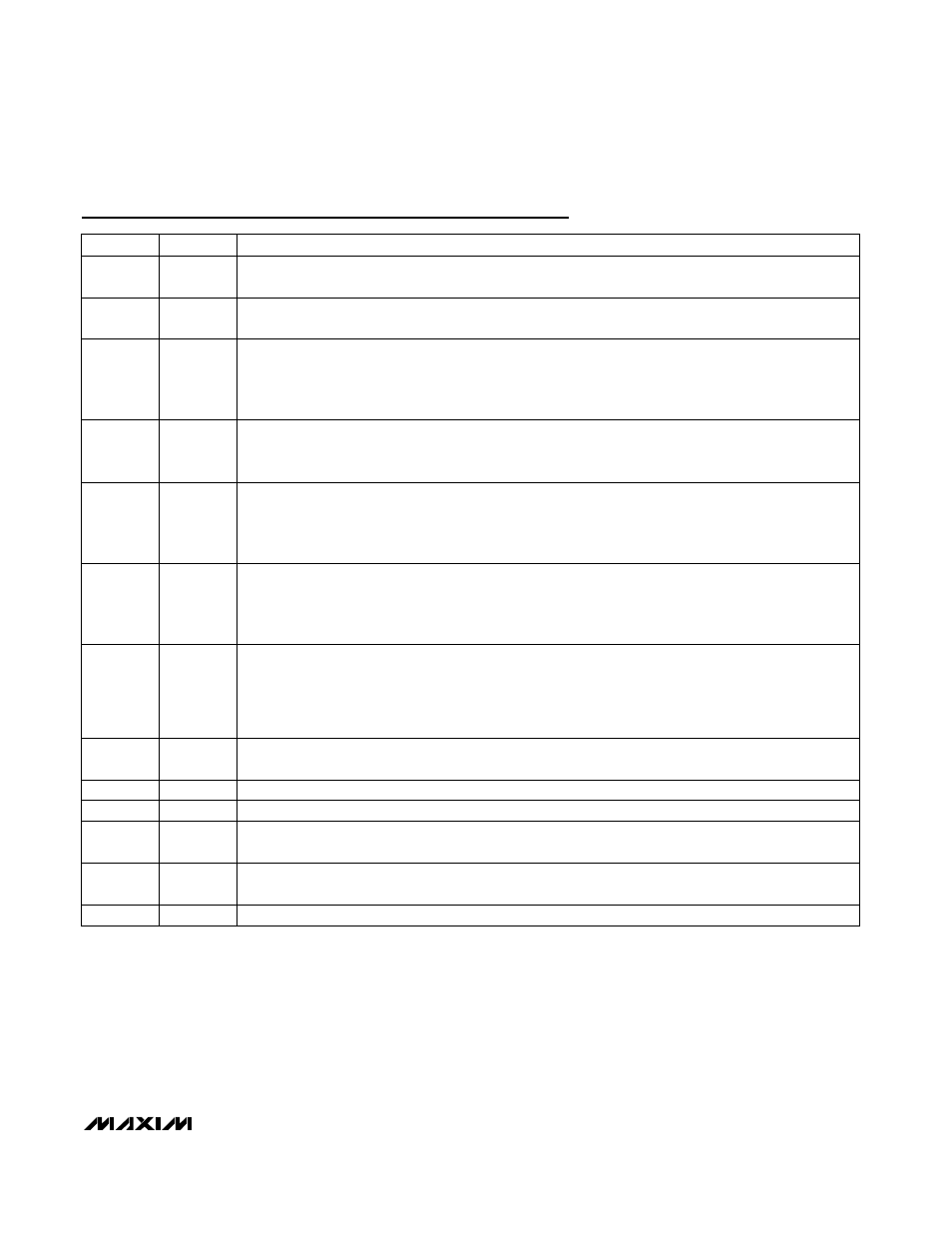
Pin description (continued) – Rainbow Electronics MAX8760 User Manual
Page 15
MAX8760
Dual-Phase, Quick-PWM Controller for AMD
Mobile Turion 64 CPU Core Power Supplies
______________________________________________________________________________________
15
PIN
NAME
FUNCTION
14
CCI
Current Balance Compensation. Connect a 470pF capacitor between CCI and FB. See the Current
Balance Compensation section.
15
FB
Feedback Input. FB is internally connected to both the feedback input and the output of the voltage-
positioning op amp. See the Setting Voltage Positioning section to set the voltage-positioning gain.
16
OAIN-
Op Amp Inverting Input and Op Amp Disable Input. When using the internal op amp for additional
voltage-positioning gain, connect to the negative terminal of current-sense resistor through a resistor as
described in the Setting Voltage Positioning section. Connect OAIN- to V
CC
to disable the op amp. The
logic threshold to disable the op amp is approximately V
CC
- 1V.
17
OAIN+
Op Amp Noninverting Input. When using the internal op amp for additional voltage-positioning gain,
connect to the positive terminal of current-sense resistor through a resistor as described in the Setting
Voltage Positioning section.
18
SKIP
Pulse-Skipping Select Input. When pulse skipping, the controller blanks the VROK upper threshold:
3.3V or V
CC
(high) = Dual-phase forced-PWM operation
REF = Dual-phase pulse-skipping operation
GND = Single-phase pulse-skipping operation
19–24
D5–D0
Low-Voltage VID DAC Code Inputs. The D0–D5 inputs do not have internal pullups. These 1.0V logic
inputs are designed to interface directly with the CPU. In normal mode (Table 4, SUS = GND), the output
voltage is set by the VID code indicated by the logic-level voltages on D0–D5. In suspend mode (Table
5, SUS = REF or high), the decoded state of the four-level S0, S1 inputs sets the output voltage.
25
VROK
Open-Drain Power-Good Output. After output voltage transitions, except during power-up and power-
down, if OUT is in regulation then VROK is high impedance. The controller blanks VROK whenever the
slew-rate control is active (output voltage transitions). VROK is forced low in shutdown. A pullup resistor
on VROK causes additional finite shutdown current. During power-up, VROK includes a 3ms (min) delay
after the output reaches the regulation voltage.
26
BSTM
Main Boost Flying Capacitor Connection. An optional resistor in series with BSTM allows the DHM pullup
current to be adjusted.
27
LXM
Main Inductor Connection. LXM is the internal lower supply rail for the DHM high-side gate driver.
28
DHM
Main High-Side Gate-Driver Output. Swings LXM to BSTM.
29
DLM
M ai n Low - S i d e G ate- D r i ver O utp ut. D LM sw i ng s fr om P GN D to V
D D
. D LM i s for ced hi g h after the M AX 8760
p ow er s d ow n.
30
V
DD
Supply Voltage Input for the DLM and DLS Gate Drivers. Connect to the system supply voltage (4.5V to
5.5V). Bypass V
DD
to PGND with a 2.2µF or greater ceramic capacitor as close to the IC as possible.
31
PGND
Power Ground. Ground connection for low-side gate drivers DLM and DLS.
Pin Description (continued)