Wiring – Turbosmart BOOST CONTROLLERS – ELECTRONIC - e-Boost2 (2005-current) – Complete User Manual User Manual
Page 5
www.TURBOSMARTONLINE.com
5
Wiring
-
The e-Boost2 must be connected to a typical automotive12 volt negative earth electrical system.
-
Soldering or Crimp on electrical connectors must be used on all electrical connections
-
Unused wires must be insulated with electrical tape so that they do not touch other wires or the chassis
-
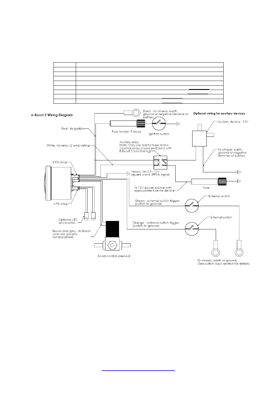
Refer to the following table and diagram for detail on wiring the e-Boost2.
Wire
Connect to
RED
+ 12 Volts switched through ignition – connect via 5 Amp fuse supplied
BLACK
Chassis, earth or ground
GREY
Solenoid wire 1 – connect using wire supplied – polarity not important
BROWN
Solenoid wire 2 - connect using wire supplied – polarity not important
YELLOW
RPM signal from ECU or negative terminal of an ignition coil OPTIONAL
WHITE
Auxiliary output – switched to ground – see diagram below OPTIONAL
GREEN
External set point switching OPTIONAL
ORANGE
External set point switching OPTIONAL
- WASTEGATES – EXTERNAL - Ultra-Gate 38 (no locking ring) (9 pages)
- WASTEGATES – EXTERNAL - Spring Combination Chart – All Wastegates (1 page)
- BLOW OFF & BYPASS VALVE KITS - Dual Port for: Nissan (Skyline GT-S and GT-R: R32, R33, R34, R35 – excluding R32GTS-t) (4 pages)
- BOOST CONTROLLERS – ELECTRONIC - Dual LED ring for e-Boost2 (2 pages)
- BLOW OFF & BYPASS VALVE KITS - Plumback: Street Unit Mazdaspeed (2 pages)
- BLOW OFF VALVES - Supersonic – Kompact (3 pages)
- BOV ADAPTERS - Subaru Forester 2.5 (3 pages)
- BLOW OFF VALVES - Plumb Back BOV Borg Warner_KKK – Kompact (2 pages)
- BOOST CONTROLLERS - Boost Tee (4 pages)
- BOOST CONTROLLERS – ELECTRONIC - Zero Function and PIN update – September 2010 (1 page)
- BOV ADAPTERS - Toyota Soarer (7 pages)
- BLOW OFF VALVES - Race Port – Universal (2 pages)
- BOOST CONTROLLERS - Dual Stage Boost Controller (5 pages)
- BOV ADAPTERS - Nissan 180SX – CA18T (5 pages)
- FUEL PRESSURE REGULATORS - FPR Series: FPR800, 1200, 2000, 3000 (3 pages)
- BOOST CONTROLLERS – ELECTRONIC - e-Boost2 (2005-current) – Quickstart Guide (3 pages)
- WASTEGATES – EXTERNAL - Ultra-Gate38 (with locking ring) (9 pages)
- BOV ADAPTERS - Subaru Liberty (Legacy) B4 (4 pages)
- WASTEGATES – EXTERNAL - Pro-Gate 50 (8 pages)
- BOOST CONTROLLERS – ELECTRONIC - e-Boost STREET 40psi – Complete Manual (20 pages)
- BOV ADAPTERS - Nissan Skyline R32 Plumb Back (3 pages)
- BOV ADAPTERS - Smart (4 pages)
- BOV ADAPTERS - Nissan Skyline R33 Plumb Back (3 pages)
- BOV ADAPTERS - Nissan 200SX (5 pages)
- WASTEGATES – EXTERNAL - Hyper-Gate45 (with locking ring) (9 pages)
- BLOW OFF & BYPASS VALVE KITS - Dual Port for: Mazdaspeed_MPS 3, 6 and CX7 (6 pages)
- BLOW OFF VALVES - Type 1 – Universal (2 pages)
- BLOW OFF & BYPASS VALVE KITS - Supersonic for: Subaru WRX (01-07), STi (01-08), Forester XT (06) (3 pages)
- BLOW OFF & BYPASS VALVE KITS - Dual Port for: Subaru WRX (01-07), STi (01-08), Forester XT (06) (4 pages)
- BOV ADAPTERS - Nissan Pulsar_Sunny GTiR (6 pages)
- BOV ADAPTERS - Subaru WRX MY98 (6 pages)
- BLOW OFF VALVES - Dual Port – Universal (2 pages)
- WASTEGATES – EXTERNAL - Comp-Gate40 (with locking ring) (9 pages)
- BLOW OFF & BYPASS VALVE KITS - Vee Port for Subaru WRX (01-07), STI (01-08), Forester XT (06) (2 pages)
- BOV ADAPTERS - Ford Falcon XR6 Turbo (4 pages)
- BLOW OFF VALVES - Plumb Back – Kompact (3 pages)
- BOV ADAPTERS - Toyota MR2 (4 pages)
- BOV ADAPTERS - Subaru Forester 2.0 (5 pages)
- BOOST CONTROLLERS – ELECTRONIC - e-Boost STREET 30psi Manual (9 pages)
- FUEL CUT DEFENDERS - FCD2 (electronic) (7 pages)
- BOOST CONTROLLERS - Single Stage Boost Controller (4 pages)
- BLOW OFF VALVES - Big Bubba BPV_BOV – Universal (3 pages)
- WASTEGATES – EXTERNAL - Power-Gate 60 (8 pages)
- BOOST CONTROLLERS – ELECTRONIC - Roll Cage Mount for e-Boost2 (2 pages)
- BLOW OFF VALVES - Supersonic – Universal (2 pages)