Turbosmart BOOST CONTROLLERS – ELECTRONIC - e-Boost2 (2005-current) – Complete User Manual User Manual
Page 4
www.TURBOSMARTONLINE.com
4
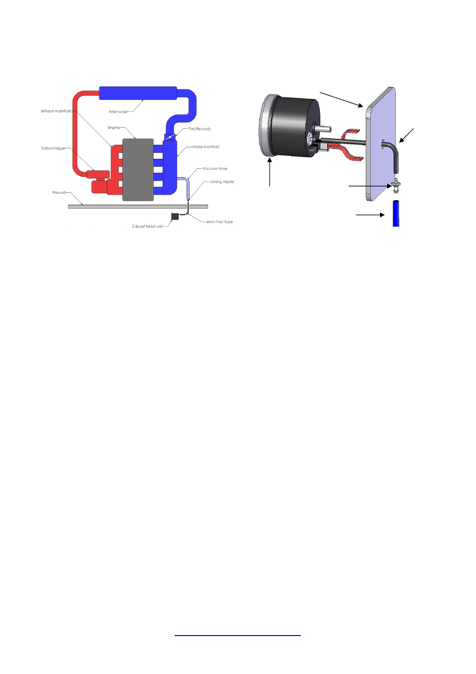
The E-Boost 2 requires a vacuum/pressure signal from the intake manifold to function. A combination of poly tube and silicone
hose is used to connect the E-boost 2 to a adequate vacuum/pressure signal. Route the poly tube from the E-boost 2 head unit
through the fire wall approximately 100mm (4”) only as the poly tube is not rated to the high temperatures of the engine bay.
Use the connecting barb to join the poly tube to the 3mm ID silicon hose at the firewall/bulkhead. Ensure the poly tube is pressed
all the way onto the connecting barb
Route the silicon hose through the engine bay and connect it to a pressure/vacuum signal from the inlet manifold. Use the supplied
tee piece if necessary.
Secure all connections with the supplied hose clamps
e-Boost 2
Silicone Hose
Joining nipple
Poly tube
Firewall
- WASTEGATES – EXTERNAL - Ultra-Gate 38 (no locking ring) (9 pages)
- WASTEGATES – EXTERNAL - Spring Combination Chart – All Wastegates (1 page)
- BLOW OFF & BYPASS VALVE KITS - Dual Port for: Nissan (Skyline GT-S and GT-R: R32, R33, R34, R35 – excluding R32GTS-t) (4 pages)
- BOOST CONTROLLERS – ELECTRONIC - Dual LED ring for e-Boost2 (2 pages)
- BLOW OFF & BYPASS VALVE KITS - Plumback: Street Unit Mazdaspeed (2 pages)
- BLOW OFF VALVES - Supersonic – Kompact (3 pages)
- BOV ADAPTERS - Subaru Forester 2.5 (3 pages)
- BLOW OFF VALVES - Plumb Back BOV Borg Warner_KKK – Kompact (2 pages)
- BOOST CONTROLLERS - Boost Tee (4 pages)
- BOOST CONTROLLERS – ELECTRONIC - Zero Function and PIN update – September 2010 (1 page)
- BOV ADAPTERS - Toyota Soarer (7 pages)
- BLOW OFF VALVES - Race Port – Universal (2 pages)
- BOOST CONTROLLERS - Dual Stage Boost Controller (5 pages)
- BOV ADAPTERS - Nissan 180SX – CA18T (5 pages)
- FUEL PRESSURE REGULATORS - FPR Series: FPR800, 1200, 2000, 3000 (3 pages)
- BOOST CONTROLLERS – ELECTRONIC - e-Boost2 (2005-current) – Quickstart Guide (3 pages)
- WASTEGATES – EXTERNAL - Ultra-Gate38 (with locking ring) (9 pages)
- BOV ADAPTERS - Subaru Liberty (Legacy) B4 (4 pages)
- WASTEGATES – EXTERNAL - Pro-Gate 50 (8 pages)
- BOOST CONTROLLERS – ELECTRONIC - e-Boost STREET 40psi – Complete Manual (20 pages)
- BOV ADAPTERS - Nissan Skyline R32 Plumb Back (3 pages)
- BOV ADAPTERS - Smart (4 pages)
- BOV ADAPTERS - Nissan Skyline R33 Plumb Back (3 pages)
- BOV ADAPTERS - Nissan 200SX (5 pages)
- WASTEGATES – EXTERNAL - Hyper-Gate45 (with locking ring) (9 pages)
- BLOW OFF & BYPASS VALVE KITS - Dual Port for: Mazdaspeed_MPS 3, 6 and CX7 (6 pages)
- BLOW OFF VALVES - Type 1 – Universal (2 pages)
- BLOW OFF & BYPASS VALVE KITS - Supersonic for: Subaru WRX (01-07), STi (01-08), Forester XT (06) (3 pages)
- BLOW OFF & BYPASS VALVE KITS - Dual Port for: Subaru WRX (01-07), STi (01-08), Forester XT (06) (4 pages)
- BOV ADAPTERS - Nissan Pulsar_Sunny GTiR (6 pages)
- BOV ADAPTERS - Subaru WRX MY98 (6 pages)
- BLOW OFF VALVES - Dual Port – Universal (2 pages)
- WASTEGATES – EXTERNAL - Comp-Gate40 (with locking ring) (9 pages)
- BLOW OFF & BYPASS VALVE KITS - Vee Port for Subaru WRX (01-07), STI (01-08), Forester XT (06) (2 pages)
- BOV ADAPTERS - Ford Falcon XR6 Turbo (4 pages)
- BLOW OFF VALVES - Plumb Back – Kompact (3 pages)
- BOV ADAPTERS - Toyota MR2 (4 pages)
- BOV ADAPTERS - Subaru Forester 2.0 (5 pages)
- BOOST CONTROLLERS – ELECTRONIC - e-Boost STREET 30psi Manual (9 pages)
- FUEL CUT DEFENDERS - FCD2 (electronic) (7 pages)
- BOOST CONTROLLERS - Single Stage Boost Controller (4 pages)
- BLOW OFF VALVES - Big Bubba BPV_BOV – Universal (3 pages)
- WASTEGATES – EXTERNAL - Power-Gate 60 (8 pages)
- BOOST CONTROLLERS – ELECTRONIC - Roll Cage Mount for e-Boost2 (2 pages)
- BLOW OFF VALVES - Supersonic – Universal (2 pages)