Turbosmart BOOST CONTROLLERS – ELECTRONIC - e-Boost STREET 30psi Manual User Manual
Installation
1
------------------------------------------------------------------------------------------------------------------------
BEFORE YOU START – IMPORTANT NOTES
Turbosmart recommends that your E-Boost Street is fitted by an appropriately qualified technician.
Consult your local tuning specialist before setting your boost pressure as setting boost beyond your engines capability can result in
severe engine damage or failure
Turbosmart recommends that the engines Air/Fuel ratio is checked once the desired boost pressure is set. Any increase in boost
pressure can cause the engine to run lean resulting in severe engine damage or failure
Turbosmart recommends that the E-Boost Street is not used in conjunction with any type of “Draw Through” induction System.
Turbosmart recommends that boost pressure is set using a Dynamometer and not on public roads.
The E-Boost Street may not be able to completely compensate for a drop in boost pressure at high RPM due to the turbocharger
operating beyond its maximum efficiency range i.e. incorrect turbocharger sizing or excessive exhaust backpressure.
The E-Boost Street cannot compensate for increases in boost pressure at high RPM due to inadequate waste gate flow capacity;
the turbo system must maintain a steady base boost curve before you start using a boost controller.
The E-Boost Street cannot be used with external waste gates that are in a poor, worn or non-serviceable condition.
For best results your turbocharger should be correctly sized for your application.
Erratic operation of electronic parts can be caused by Electro Magnetic Interference (EMI). EMI can be generated by aftermarket
ignition systems such as CDI which, if wired incorrectly, generate large amounts of EMI through the vehicles electrical system. This
can cause items such as ECU’s and boost controllers to be effected. Please follow ignition system installation instructions VERY
carefully to avoid EMI affecting the E-Boost Street. Sometimes, using resistor type spark plugs can reduce this problem.
The E-Boost Street is not waterproof and must be mounted inside the cabin. The unit has an operating temperature range of -5
O
C
to 70
O
C.
INSTALLATION
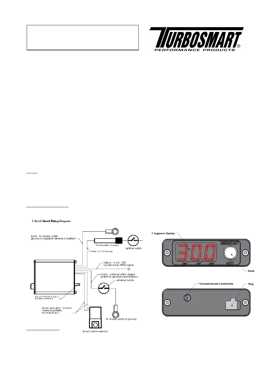
Wiring
Red Wire – +12 Volts switched through ignition – connect via 5 Amp fuse supplied
Black Wire – Chassis, earth or ground
Yellow Wire – To 3.5V – 12V Square wave (RPM) Signal
Green Wire – External set point switching or auto dimming trigger wire (Ground to activate)
Brown and grey wire – to boost control solenoid (Polarity not important)
Vacuum/pressure signal
Route the supplied hose through the engine bay and connect it to a pressure/vacuum signal from the inlet manifold.
Solenoid mounting
The control solenoid is rated to a maximum temperature of 100 degrees Celsius (212 degrees Fahrenheit), ensure that it is
mounted a minimum of 250mm (10 Inches) away from the heat of the turbo or exhaust manifold, otherwise heat shielding is
required.
Mount the E-Boost Street solenoid in an appropriate position in the engine bay with the mounting kit supplied.
Document Type:
Instruction Manual
Product Name:
E-Boost Street 30psi
Product Description:
Electronic boost controller
Product Number:
TS-0302-1001
Unit Layout