Wind ring installation, Installation – Grain Systems Tanks PNEG-1095 User Manual
Page 66
6. Installation
66
PNEG-1095 FCDL 4.00" Corrugation Externally Stiffened Grain Bin
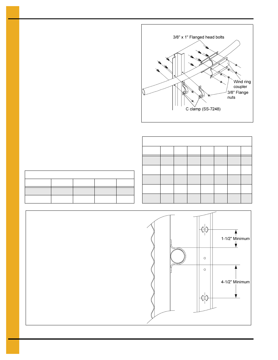
Wind Ring Installation
1. Sidedraw systems may require additional
wind rings. They must be attached at the
beginning of assembly because they go
on the upper most rings.
2. To connect wind ring pipe to the stiffeners,
field drill 3/8'' holes through the flange of the
stiffener.
3. Attach wind ring pipe section to stiffener using
two (2) 3/8" x 2-1/2" U-bolts and nuts.
4. Connect section of wind ring pipe to the first
section by sliding the male end into the female
end of pipe. Fasten together using two (2)
wind ring couplers and six (6) 3/8" x 1"
flanged head bolts with nuts. Couplers should
be centered on the seam of pipes.
5. Sidedraw wind ring used in conjunction with
standard wind ring is placed in the 4
th
ring.
Standard sidedraw wind ring is placed in the
2
nd
ring.
Figure 6W
Figure 6X
Standard Wind Ring Placement (Ring #)
Rings
42'
48'
54'
60'
13
-
-
2
2
14
2
2
2
-
Wind Ring Requirements
Rings
30'
33'
36'
42'
48'
54'
60'
10
--
--
1
1
1
1
1
11
--
1
1
1
1
1
1
12
1
1
1
1
1
1
1
13
1
1
1
1
1
1
1
14
--
--
--
1
1
1
--
NOTE: Wind rings must be installed
in relation to the ladder rungs as
shown here to ensure compliance
with O.S.H.A., regulations.