Rough Country 770S User Manual
Page 12
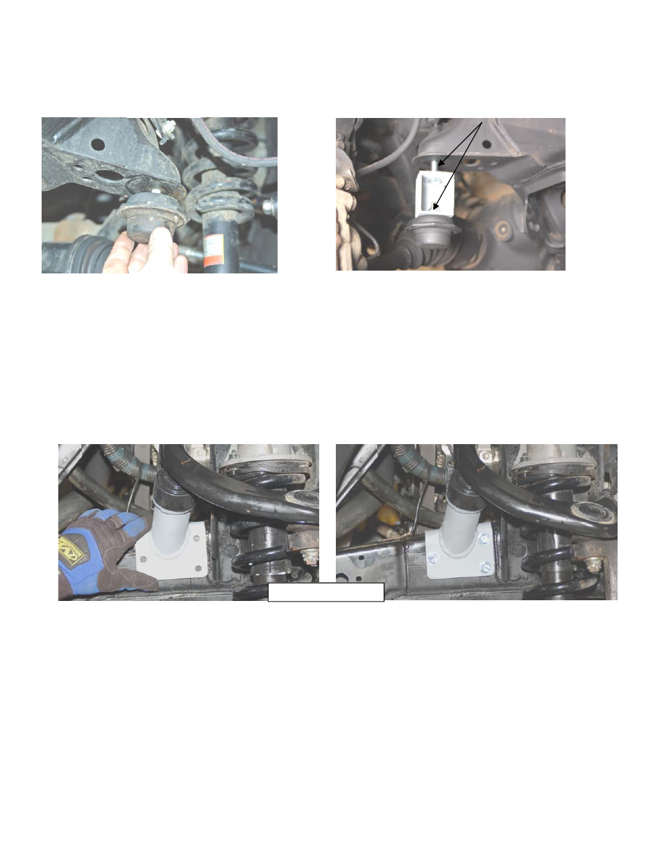
PHOTO 48
65. On both sides of the vehicle, check the routing of the brake lines and the ABS wiring harness. There must be no
pinching, rubbing, or stretching of either component. At full droop, cycle the steering from lock to lock while observ-
ing the movements of these components. Recheck periodically.
66. If installing a tire larger than a 33x12.50, skip to the next section. Cutting of the body mount must be completed for
larger than 33” tires.
67. Reinstall the wheels and lower to the ground. Torque the lug nuts to the factory specifications.
68. With the vehicle on the ground, using a 19mm wrench torque the lower A arm cam bolts to 100 ft.lbs.
69. Recheck all hardware for proper installation and torque at this time.
70. Locate and install the new upper control arm bump-stop bracket / bump-stop on the frame behind the upper control
arm as shown in PHOTO 49. Mark and drill with a 11/32” drill bit. Reinstall bracket on frame with supplied 3/8” x 1”
self tapping bolts and tighten. See PHOTO 50. Repeat for opposite side.
PHOTO 47
62. Using a 3” adjustable wrench, or strap wrench, remove the factory bump stop. See PHOTO 47.
63. Bolt the factory bump stop onto the new bracket using the supplied 10mm lock nut. Tighten nut using a 17mm
wrench. See PHOTO 48.
64. Install the new bump-stop and bracket on the frame with the supplied 10mm x 35mm bolt using a 17mm wrench.
Passenger side shown
PHOTO 49
PHOTO 50