2 mounting and installation instructions, Mounting, Coding – VEGA VEGAMET 614 User Manual
Page 10: Mounting and installation instructions
10
VEGAMET 614
A o
B o
C o
1 o
2 o
3 o
o
o
o
7 o
8 o
9 o
o
o
12 o
N
L1
0…10 V
DISBUS
VEGA
A o
B o
C o
1 o
2 o
3 o
4 o
5 o
6 o
7 o
8 o
9 o
10 o
11 o
12 o
N
L1
0…10 V
DISBUS
VEGA
-
+
-
+
Mounting and installation instructions
Mounting
Each series 600 signal conditioning instru-
ment consists of a plug-in socket for carrier
rail mounting DIN 46 277 and a module unit.
The supply voltage can be connected to
terminals 17 and 18.
For neighbouring series 600 signal condition-
ing instruments, it is possible to continue the
connection L1 and N directly via the supplied
jumpers. The same is valid for the connection
of VEGAMET voltage output 0 … 10 V (termi-
nals 15 and 16) and for DISBUS output (ter-
minals 9 and 10).
Note!
The jumpers must never be used with single
instruments or at the terminating end of an
instrument row. If this is not observed, there
is danger of coming in touch with the operat-
ing voltage or causing a short-circuit.
VEGAMET 614 Ex signal conditioning instru-
ment is intrinsically safe and must not be
installed in hazardous areas.
Before setup, the Ex separating chamber
must be plugged into VEGAMET 614 Ex as
shown in the illustration.
Safe operation is ensured only if the operat-
ing instructions manual and the EC type
approval certificate are observed. VEGAMET
614 Ex must not be opened.
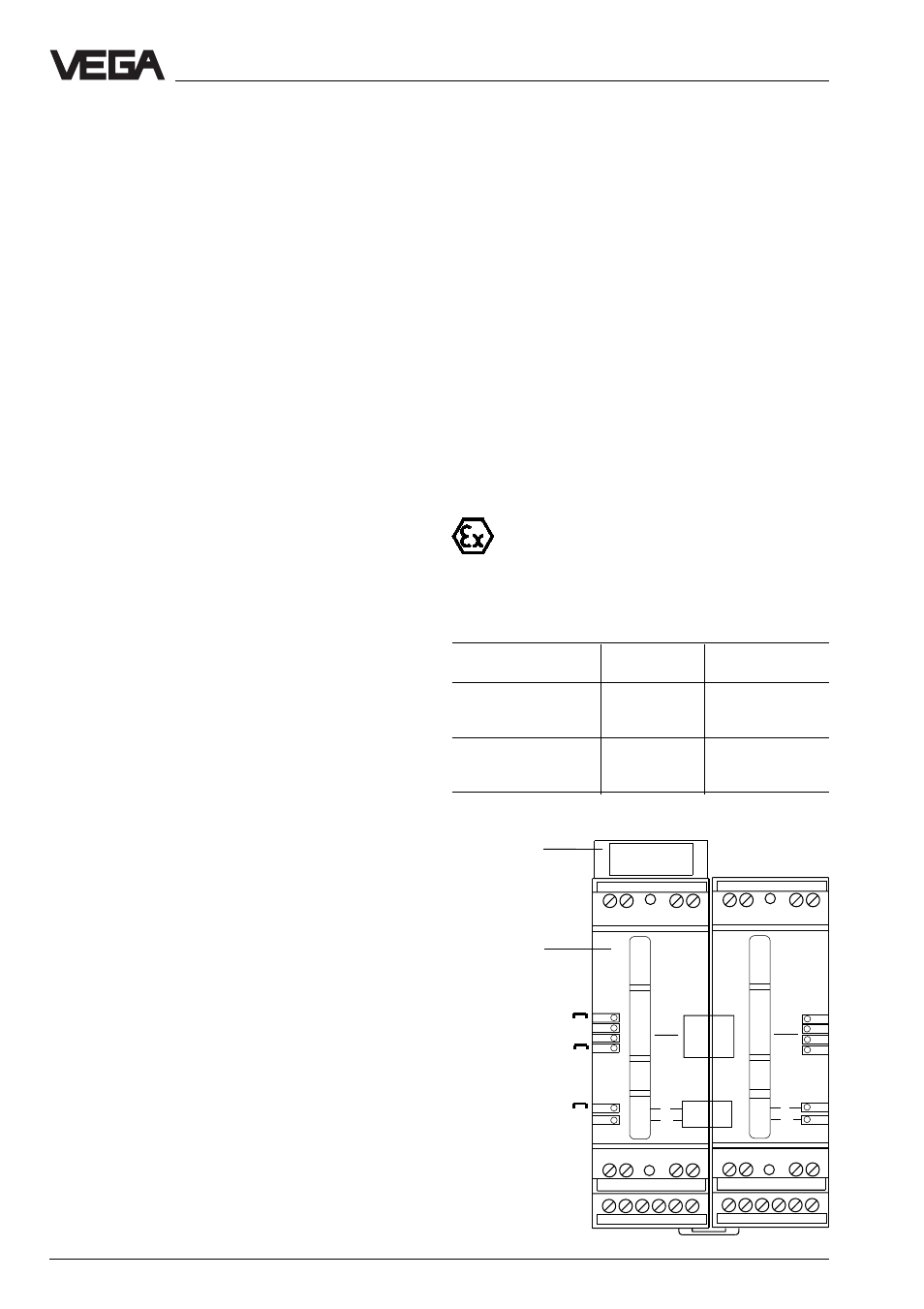
2 Mounting and installation instructions
left
right
Separating chamber
(must always by
plugged in on the left
with Ex instruments)
Ex coding
Direct supply for
voltage output
0 … 10 V and
DISBUS
Direct connection
for supply voltage
Jumpers
Coding
To avoid interchanging the various signal
conditioning instruments, the plug-in socket
is provided with pins and the signal condi-
tioning instruments with corresponding gaps
(mechanical coding).
Instrument coding ensures through differ-
ently positioned coding pins that the various
series 600 signal conditioning instruments
are not interchanged.
An Ex coding with inserted coding pins en-
sures that the non-Ex and Ex instruments are
not interchanged.
On VEGAMET 614 Ex, the supplied
coding pins (instrument coding pin
and Ex coding pin) must be inserted
by the user according to the below table.
Instrument
Ex
coding
coding
VEGAMET 614
right 1
––
left B
right B
VEGAMET 614 Ex
right 1
left A
left B
right B