Display screen diagram product diagram (cont.), E51h5 – Veris Industries E51H5 Install User Manual
Page 6
ZL0109-0C
Page 6 of 32
©2013 Veris Industries USA 800.354.8556 or +1.503.598.4564 / [email protected] 10131
Alta Labs, Enercept, Enspector, Hawkeye, Trustat, Aerospond, Veris, and the Veris ‘V’ logo are trademarks or registered trademarks of Veris Industries, L.L.C. in the USA and/or other countries.
Other companies’ trademarks are hereby acknowledged to belong to their respective owners.
Installation Guide
Power Monitoring
E51H2, E51H5
TM
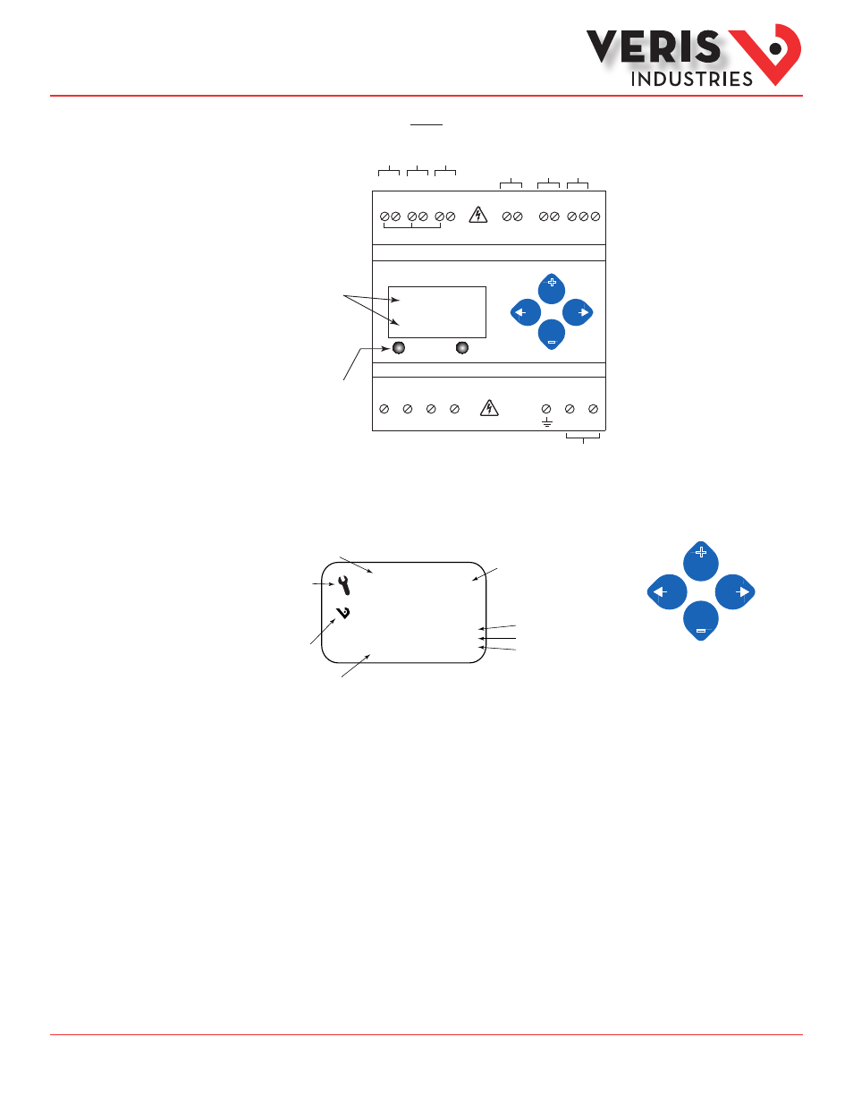
Alarm
Energy
Two 5-character rows
of display text.
Top row alphanumeric;
Bottom row numeric only
The red Alarm LED lights
when any of the 3 phase
voltages drop below the
selected threshold.
The green Energy LED lights
when the pulse 1 input
contacts are active or closed.
CONTROL POWER
0.1A 50/60 Hz
A
B
C
N
1
2
Pulse Inputs
1
2
+ - S
RS-485
VA
VB
VC
Neutr
al
Ear
th
Con
trol
Po
we
r
UL: 90V
L-N
- 600V
L-L
CE: 90V
L-N
- 300V
L-N
VOLTAGE INPUTS
CAT III 50/60 Hz
+
–
Pulse Input 1
Pulse Input 2
BA
Cnet
Shield
(X2)
A
(X1) (X2)
B
(X1) (X2)
C
(X1)
IA
IB
IC
X2 X1 X2 X1 X2 X1
CT Inputs
1 or 0.333 VAC
E51H5
Tx
Rx
ERR
♥
Screen Name or Units
Diagnostic Alert:
indicates that one or
more of the alarm
bits (Binary_Objects
1-15) are active.
Logo
Numeric Data
Alive Indicator
RS-485 Equipped Units Only:
Transmit Data
Receive Data
Receive Data Error
LCD Screen:
Buttons:
+
–
(Up)
Select
(Right)
Next
(Down)
Select
(Left)
Back
Display Screen
Diagram
Product Diagram
(cont.)