3 wiring – Veris Industries VH7200 SERIES Install User Manual
Page 3
3
Wiring
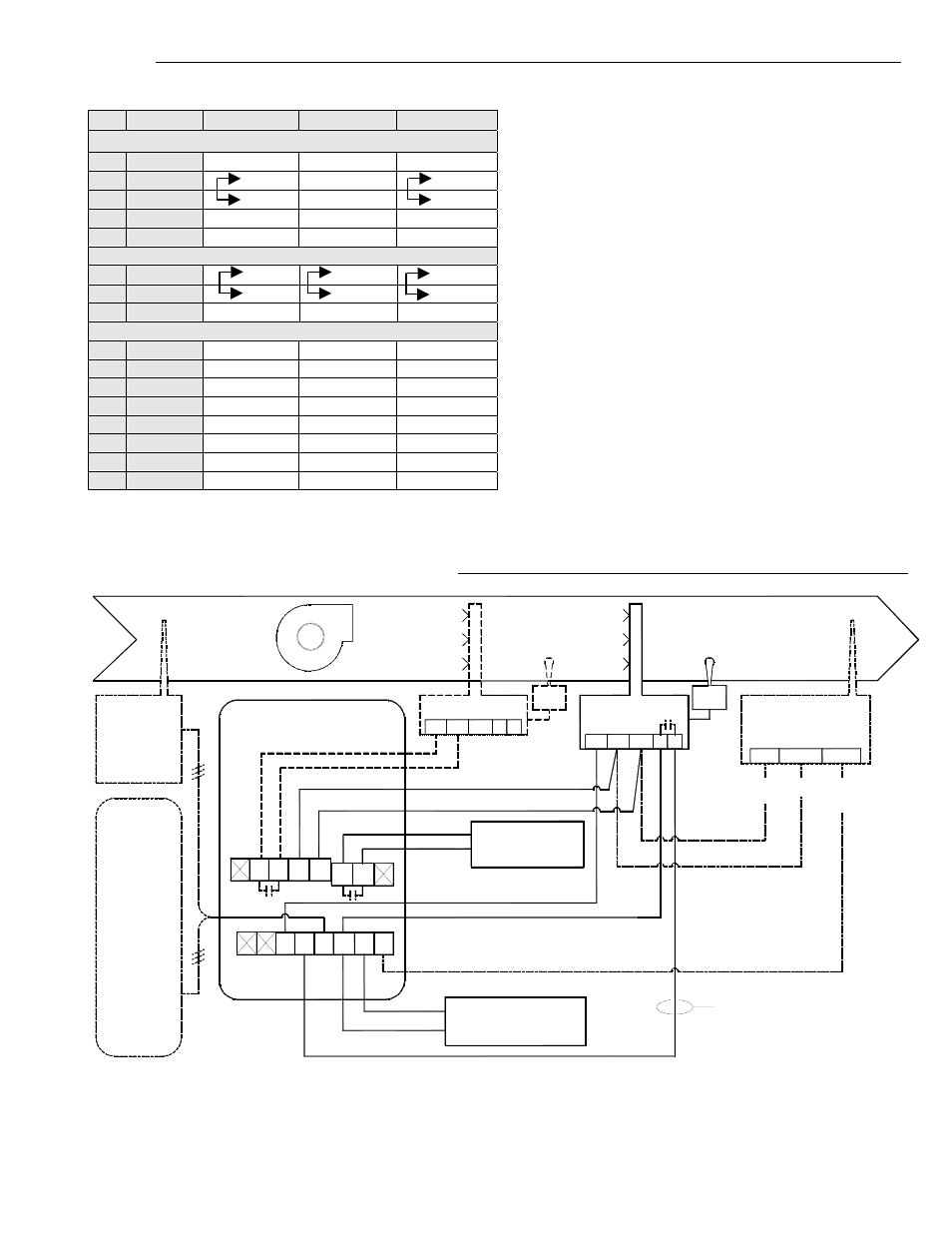
Terminal identification & screw terminal arrangement
Wiring notes:
Note 1:
Reference of the analog 0-10 Vdc control signal
is the common of the power supply of the
humidistat. (terminal C)
Note 2:
Electromechanical dry contact is to be used with
the binary input. Electronic triacs cannot be used
as mean of switching for the input. The switched
leg to the input for the input to activate is
terminal Scom
Note 3:
The transformer of the unit provides power to
the humidistat and any additional loads wired
to the humidistat.
Note 4:
Both the remote humidity sensors ( HS & HL
terminals ) use 0 to 10 Vdc type humidity
sensors.
Detailed wiring diagram for model VH7270K1000
Part Number
VH7270K
VH7270D/F
VH7200A
Top left terminal block
1
Not used
Not used
Not used
2
HUM
X
Not used
X
3
HUM
X
Not used
X
4
R
X X X
5
C
X X X
Top right terminal block
6
DEH
X X X
7
DEH
X X X
8
Not used
Not used
Not used
Bottom terminal block
9
Not used
Not used
Not used
10
Not used
Not used
Not used
11
HUM 0-10
X X
Not used
12
DI1
X X X
13
HS
X X X
14
SCOM
X X X
15
OS
X X X
16
HL
X X
Not used
Fig.5 : VH7200’s wiring terminals
Fig.6 : VH7270F1000 wiring diagram
FLOW
SWITCH
HUM
0-10
VH7270K1000
HUMIDITY CONTROLLER
Note:
When a remote
humidity
transmitter
is connected to
the VH7200,
it's internal
humidity
sensor is
tomatically
disabled.
au
VH2030W1000
OPTIONAL
WALL
MOUNTED
HUMIDITY
TRANSMITTER
or
VH2030D1000
OPTIONAL
DUCT
MOUNTED
HUMIDITY
TRANSMITTER
Dry contact
Dehumidification
and/or
air exchanger
R
C
HS
DI1
OS
Scom
HL
X
X
24V Com
0-10
(0-10 Vdc)
HUMIDIFIER
S202
00
OP
TE
R
0E1000 or S2000D10
TIONAL OUTDOOR
MPERATURE SENSO
24 Vac
BL
AC
K
O
R
AN
G
E
R
ED
VH2030D1000
HUMIDITY TRANSMITTER
( OPTIONAL HIGH LIMIT )
COM.
0-10 Vdc
R.A.
S.A.
DEH
HUMHUM
(On/Off) HUMIDIFIER
H
FLOW
SWITCH
H
Binary Input "Di1" Set
for "SERVICE" alarm
Dry contact
DEH
Humidification Output :
( On/Off ) or ( 0-10 Vdc )
Refer to parameter:
"SeqOpera"