Veris Industries VH7200 SERIES Install User Manual
Page 2
2
Features overview
•
Internal RH sensor and optional remote RH input with embedded humidification and dehumidification sequence
of operation.
•
Humidity set point reset based upon outdoor temperature sensing for added flexibility.
•
Proportional high limit input to prevent over-humidification due to supply humidity condensation.
•
Lockable keypads for tamper proofing. No need for extra humidistat guard.
• Programmable binary input for added flexibility. The input can be programmed as the following:
- None: No function will be associated with the input
- Service: a backlit flashing Service alarm will be displayed on the humidistat LCD screen when the input is
energized. It can be tied in to the AC unit control card, which provides an alarm in case of malfunction.
- Canister: a backlit flashing Canister alarm will be displayed on the humidistat LCD screen when the input is
energized. It can be tied to a Dry contact output supplied by others.
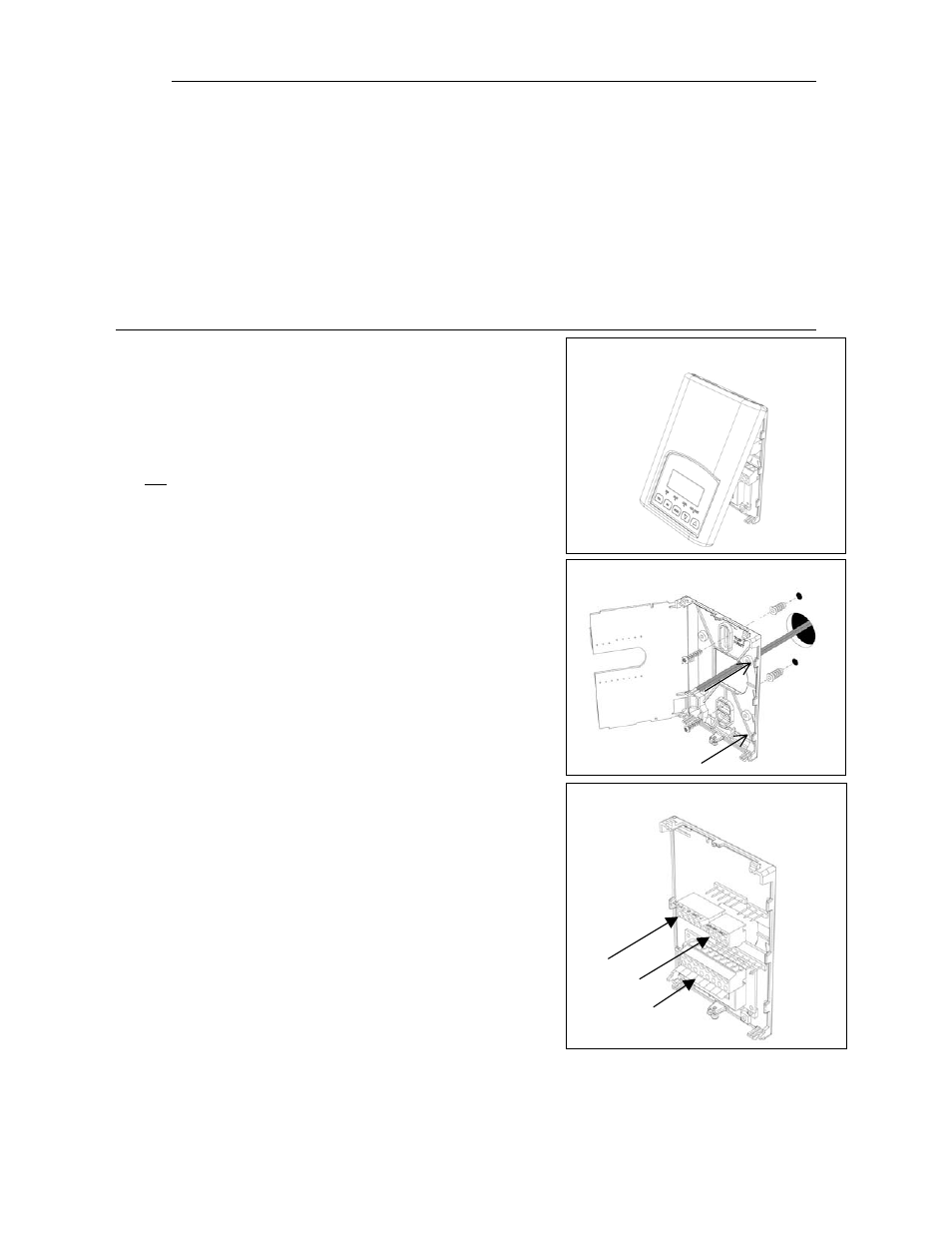
Fig.2
Fig.3
Fig.4
Installation
•
Remove security screw on the bottom of humidistat cover.
•
Open up by pulling on the bottom side of humidistat.
•
Remove Assembly and remove wiring terminals from sticker.
(Fig. 2)
A) Location:
1- Should
not be installed on an outside wall.
2- Must be installed away from any heat source.
3- Should not be installed near an air discharge grill.
4- Should not be affected by direct sun radiation.
5- Nothing must restrain vertical air circulation to the
humidistat.
B) Installation:
1- Swing open the humidistat PCB to the left by pressing the
PCB locking tabs. (Fig. 3)
2- Pull out cables 6” out of the wall.
3- Wall surface must be flat and clean.
4- Insert cable in the central hole of the base.
5- Align the base and mark the location of the two mounting
holes on the wall. Install proper side of base up.
6- Install anchors in the wall.
7- Insert screws in mounting holes on each side of the base.
(Fig. 3)
8- Gently swing back the circuit board on the base and push
on it until the tabs lock it.
10- Strip each wire 1/4 inch.
11- Insert each wire according to wiring diagram.
13- Gently push back into hole excess wring (Fig. 4)
14- Re-Install wiring terminals in correct location. (Fig. 4)
15- Reinstall the cover (top side first) and gently push back
extra wire length into the hole in the wall.
16- Install security screw.
For VH7270D1000 duct-mount model only:
1- Make 1” diameter hole in duct wall
2- Insert the duct sensor and fix the electrical box to the
duct wall in the vertical position (respect airflow
direction).
3- Install the humidistat to the electrical box using the
supplied screws (2).
4- Follow steps 1-16 above.
Note: For dimensions please see page 14