Wiring, Warning, Diagram 3: 1-phase direct voltage connection 2 ct – Veris Industries E51C3A Install User Manual
Page 8: Diagram 4: 3-phase 3-wire 3 ct no pt
ZL0122-0A
Page 8 of 34
©2013 Veris Industries USA 800.354.8556 or +1.503.598.4564 / [email protected] 09132
Alta Labs, Enercept, Enspector, Hawkeye, Trustat, Aerospond, Veris, and the Veris ‘V’ logo are trademarks or registered trademarks of Veris Industries, L.L.C. in the USA and/or other countries.
Other companies’ trademarks are hereby acknowledged to belong to their respective owners.
Installation Guide
Power Monitoring
E51C2A, E51C3A
TM
RISK OF ELECTRIC SHOCK OR PERMANENT EQUIPMENT DAMAGE
CT negative terminals are referenced to the meter’s neutral and may be at elevated voltages
· Do not contact meter terminals while the unit is connected
· Do not connect or short other circuits to the CT terminals
Failure to follow these instructions may cause injury, death or equipment damage.
WARNING
Wiring
N L1
X2
X1
White
Black
A
B
C
N
X1
X2
X1
X2
X1
X2
A
B
C
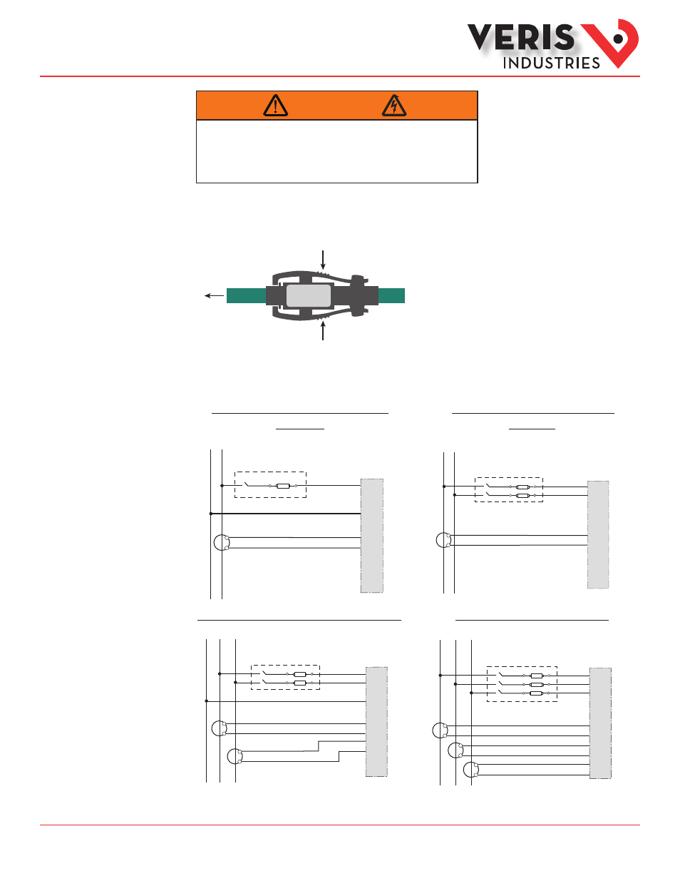
Diagram 1: 1-Phase Line-to-Neutral 2- Wire
System 1 CT
Diagram 2: 1-Phase Line-to-Line 2-Wire
System 1 CT
L1 L2
X2
X1
X2
X1
A
B
C
N
A
B
C
N
White
Black
White
Black
X1
X2
X1
X2
X1
X2
L1 L2
X2
X1
A
B
C
N
A
B
C
White
Black
X1
X2
X1
X2
X1
X2
Diagram 3: 1-Phase Direct Voltage Connection 2 CT
L1 L2 L3
X2
X1
A
B
C
N
A
B
C
X2
X1
X2
X1
White
Black
White
Black
White
Black
X1
X2
X1
X2
X1
X2
Diagram 4: 3-Phase 3-Wire 3 CT no PT
Use System Type 11 (2L)
Use System Type 12 (2L + 1n)
Use System Type 31 (3L)
Use System Type 10 (1L + 1n)
1. Connect the CT output leads to the E5xxxA meter inputs according to the following diagrams. The white wire is the X1 lead.
Observe correct CT orientation.
2. Squeeze the ribbed sections of the CT connector and pull the rope out of the connector to open.
3. Wrap the rope style CT around the conductor to be monitored.
4. Snap the connector back together securely, ensuring there is no dust or debris in the closure area.