Standard modbus default settings, Modbus point map overview (cont.) – Veris Industries E51C3A Install User Manual
Page 19
ZL0122-0A
Page 19 of 34
©2013 Veris Industries USA 800.354.8556 or +1.503.598.4564 / [email protected] 09132
Alta Labs, Enercept, Enspector, Hawkeye, Trustat, Aerospond, Veris, and the Veris ‘V’ logo are trademarks or registered trademarks of Veris Industries, L.L.C. in the USA and/or other countries.
Other companies’ trademarks are hereby acknowledged to belong to their respective owners.
Installation Guide
Power Monitoring
E51C2A, E51C3A
TM
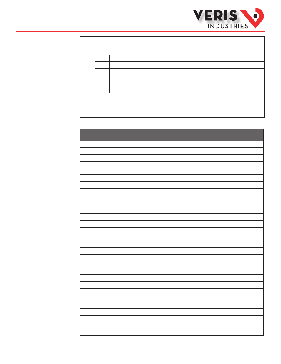
R/W
R=read only
R/W=read from either int or float formats, write only to integer format.
NV
Value is stored in non-volatile memory. The value will still be available if the meter experiences a power loss and reset.
Format
UInt
Unsigned 16-bit integer.
SInt
Signed 16-bit integer.
ULong
Unsigned 32-bit integer; Upper 16-bits (MSR) in lowest-numbered / first listed register (001/002 = MSR/LSR).
SLong
Signed 32-bit integer; Upper 16-bits (MSR) in lowest-numbered / first listed register (001/002 = MSR/LSR).
Float
32-bit floating point; Upper 16-bits (MSR) in lowest-numbered / first listed register (257/258 = MSR/LSR). Encoding is
per IEEE standard 754 single precision.
Units
Lists the physical units that a register holds.
Scale
Factor
Some Integer values must be multiplied by a constant scale factor (typically a fraction), to be read correctly. This is done to allow
integer numbers to represent fractional numbers.
Range
Defines the limit of the values that a register can contain.
Standard Modbus
Default Settings
Setting
Value
Modbus
Register
Setup Password
00000
–
Reset Password
00000
–
System Type
40 (3 + N) Wye
130
CT Primary Ratio (if CTs are not included)
100A
131
CT Secondary Ratio
QNAN
132
PT Ratio
1:1 (none)
133
System Voltage
600 V L-L
134
Max. Theoretical Power
(Analog Output: full scale (20mA or 5V))
104 kW
135
Display Mode
1 (IEEE units)
137
Phase Loss
10% of System Voltage (60V), 25% Phase to Phase Imbalance
142, 143
Pulse Energy
1 (kWh/pulse)
144
Demand: number of sub-intervals per interval
1 (block mode)
149
Demand: sub-interval length
900 sec (15 min)
150
Modbus Address
001
–
Modbus Baud Rate
19200 baud
–
Modbus Parity
None
–
Log Read Page
0
158
Logging Configuration Register
0
159
Log Register Pointer 1
3 (Import Real Energy MSR)
169
Log Register Pointer 2
4 (Import Real Energy LSR)
170
Log Register Pointer 3
5 (Export Real Energy MSR)
171
Log Register Pointer 4
6 (Export Real Energy LSR)
172
Log Register Pointer 5
29 (Real Demand)
173
Log Register Pointer 6
30 (Reactive Demand)
174
Log Register Pointer 7
31 (Apparent Demand)
175
Log Register Pointer 8
155 (Month/Day)
176
Log Register Pointer 9
156 (Year/Hour)
177
Log Register Pointer 10
157 (Minutes/Seconds)
178
Modbus Point Map
Overview (cont.)