Veris Industries Badger 200 SERIES Install User Manual
Page 7
7
7) When connecting to a Badger Meter flow monitor/
transmitter, locate the section of terminal strip on the
monitor labeled “SENSOR INPUT” or “SENSOR”.
Connect the red wire to “IN”, "SIGNAL(+)" or "SIGNAL"
terminal and the black wire to “GND", "SIGNAL(-)”, or
"COM" terminal and the shield drain wire (if applicable)
to “SLD”.
8) When interfacing with other equipment, the signal wave
forms and power requirements are as shown in the
specifications section. Refer to technical bulletin DTB-
058 at www.badgermeter.com
Electrical Installation "High Temperature" sensors
1) Route a cable from the sensor to a Badger Meter flow
monitor/transmitter. The cable may be run up to 2000
feet, using 2-conductor shielded 20 AWG or larger
stranded copper wire. Be sure to leave enough flexibility
in the cable or conduit to allow for future service of sen-
sor, if necessary.
2) Connect to cable inside sensor electronic housing on
Series 220 sensors or attach to the sensor cable on the
Series 225/226 and connect with standard wire nuts.
3) When connecting to a Badger Meter flow monitor or
transmitter, locate the section of terminal strip on the
monitor labeled “SENSOR INPUT” or “SENSOR”.
Connect the red wire to “ IN”, "SIGNAL(+)" or
"SIGNAL" terminal and the black wire to “GND",
"SIGNAL(-)”, or "COM" terminal and the shield drain
wire (if applicable) to “SLD”.
4) When interfacing with other equipment, the signal wave
forms and power requirements are as shown in the
specifications section.
Electrical Installation "Magnetic" sensors
The magnetic sensor has a custom wire connector tha
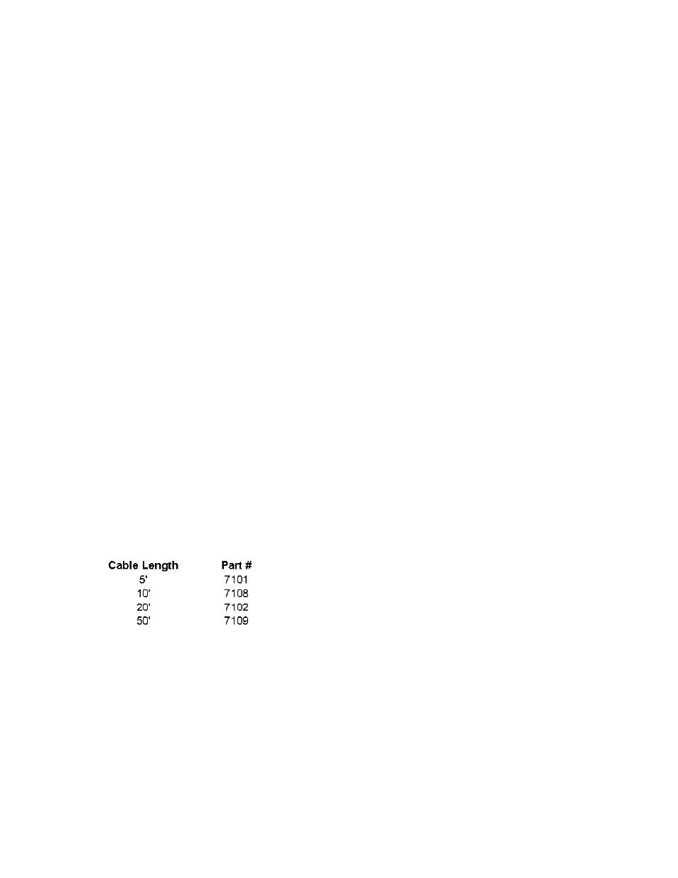
connects to the series 1400 monitor only. The cable may be
extended up to 100 feet from the sensor. If extension cables
are needed they may be ordered from Badger Meter.
Electrical Installation (FM Sensors)
The Badger
®
Series 200 sensor is approved, as an entity, as
intrinsically safe when installed in conformance with Bad-
ger Meter installation drawings 06-480-001 or 06-480-002
(samples shown on Page 10) as specified on the blue label
identifying an intrinsically safe sensor.
Entity approval implies that only the sensor is approved as
intrinsically safe. Unless power supplies, equipment, and
instruments connected to the sensor are each rated either
explosion-proof or intrinsically safe, these devices cannot be
installed in a hazardous area. The referenced installation
drawing shows such apparatus located in a non-hazardous
location. Proper interfacing between the hazardous and non-
hazardous areas must be provided. It is of absolute impor-
tance that this interface be constructed and that all wiring be
performed by qualified contractors. To ensure the intrinsic
safety of the installation, the connection of the intrinsically
safe sensor to instruments and or power supplies must take
place using an approved intrinsically safe barrier located in a
non-hazardous area. These barriers, listed below, are read-
ily available from various suppliers.
Manufacturer:
Barrier:
Crouse-Hinds Spec 504
Cat No.SB19140M0715
Measurement Technology Ltd.
MTL 715+ 15 V
R Stahl Intrinspak
9001/1-158-150-10