Veris Industries Badger 200 SERIES Install User Manual
Page 5
5
the liquid flow direction. Tighten the positioning collar Allen
screws to lock the sensor tube assembly in position. Note:
As a backup to the flow direction arrow label on the tube
assembly, there is a smaller hole located beside one of the
sighting holes in the tube, to also indicate the upstream side
of the tube assembly.
If the pipe is depressurized and drained
1) Drill or cut a 1 7/8 inch hole in the pipe with a drill or
hole saw. Note the pipe wall thickness for use in calcu-
lating sensor assembly depth. A location on the top of
the pipe is best for overall performance and service life;
however, any radial location on the top half of the pipe is
acceptable. Allow a minimum of ten pipe diameters up-
stream and five downstream from the sensor of straight
unobstructed pipe to allow full development of the flow
profile.
2) Install either a service saddle or welded pipe fitting (2
inch female NPT) on the outside diameter of the pipe
over the 1 7/8 inch hole.
3) Install the Badger Meter isolation valve and nipple onto
the fitting using pipe thread sealant or Teflon
®
tape on all
threads.
4) Install the Badger Meter hex mounting adapter onto the
valve assembly. Use pipe thread sealant on the adapter.
Tighten the hex adapter so that no stud is aligned with
the center-line of the pipe. This could interfere with final
sensor alignment. Measure depth and set the height of
the nuts of the hex mounting adapter.
5) Open the bleed petcock valve on the hex adapter to re-
lieve the pressure as the sensor tube is installed. Care-
fully hand insert the Badger Meter hot tap flow sensor
tube into the hex mounting adapter. The sleeve should
be inserted past the top two O-rings in the adapter
(approx. 1 - 1 1/4 inches). Take care not to push the
tube in too far as the impeller could be damaged if it
strikes the closed valve.
6) Even if the sensor is installed with system drained,
Badger Meter recommends that a HTT, hot tap insertion/
removal tool be purchased for future service. This tools
allows the sensor tube assembly to be removed from the
pipe line without draining the entire loop where the sen-
sor is mounted.
7) In a fully depressurized and drained pipe, the sensor
tube assembly may be installed by hand. Carefully
and very slowly open the isolation valve to relieve any
pressure that may have built up. Fully open the isolation
valve. Push the sensor tube into the pipe with a slight
twisting motion. Guide the sensor collar holes over the
three hex adapter studs until the collar rests on the nuts.
Hex nuts should have been previously set to the correct
height. Install the three lock nuts onto these studs at the
top of the positioning collar and securely tighten.
8) Loosen the two set screws in the positioning collar with
a 3/32 inch Allen wrench. Align the sensor sight holes
along the pipe axis using the alignment rod provided in
the installation kit supplied with the sensor. Ensure that
the flow label arrow on the sensor matches the liquid
flow direction inside the pipe. Tighten the positioning col-
lar set screws. Note: As a backup to the flow label arrow,
there is a small hole located beside one of the sighting
holes to also indicate the upstream side of the sensor.
INSTALLATION INTO A PRESSURIZED PIPELINE USING
MODEL HTT.
For information on installing hot tap sensor with older 225H
consult technical bulletin DID-001
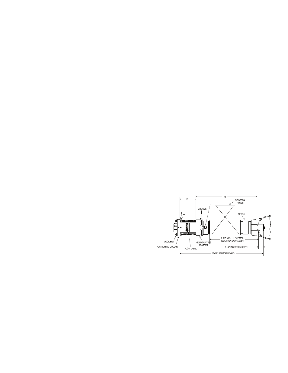
For pipe sizes 2½” and above; all Badger Meter sensors are
inserted 1 1/2” from the inside wall of the pipe. The insertion
depth is controlled by the position of the hex nuts on the
three threaded rods. The formula below defines the distance
between the top of the sensor hex mounting adaptor and
the bottom of the positioning collar (the top of the hex nut).
Reference Figure 3.
D = 16 3/8” - ( H + Pipe Wall Thickness + 1.5 “ )
Example: If sensor is installed in a 8 inch Sch 80 pipe with
a pipe wall thickness of 1/2 inch and the “H”
dimension is 10 inches then the calculation
would be as below:
D = 16 3/8 - ( 10 inches + 0.5 inches + 1.5 inches)
D = 4 3/8”
BLEED VALVE
HEX NUT
JAM NUT
Figure 3