Veris Industries Badger 200 SERIES Install User Manual
Page 12
12
Impeller Assembly and Shaft Replacement
If you are replacing an existing Badger Meter sensor and
have already calibrated your flow monitor/transmitter, no
calibration changes are necessary. For installation of a new
flow monitor or for relocation of a sensor in a new pipe size,
please refer to the calibration instructions in flow monitor
manual.
1) Depressurize pipe from which sensor is to be removed.
If the sensor is one of the Series 225/IR225 or 226/
IR226, consult the installation section on hot tap sen-
sors.
NEVER disturb the securing lock nuts with pipe un-
der pressure without hot tap insertion tool Model HTT
installed.
2) Remove the three lock nuts that secure the positioning
collar to the threaded rods of metal sensor.
NOTE: Before removing lock nuts, record the dimension
from top of 2 inch NPT adapter to the bottom of the position-
ing collar. This dimension will be required later to reinstall.
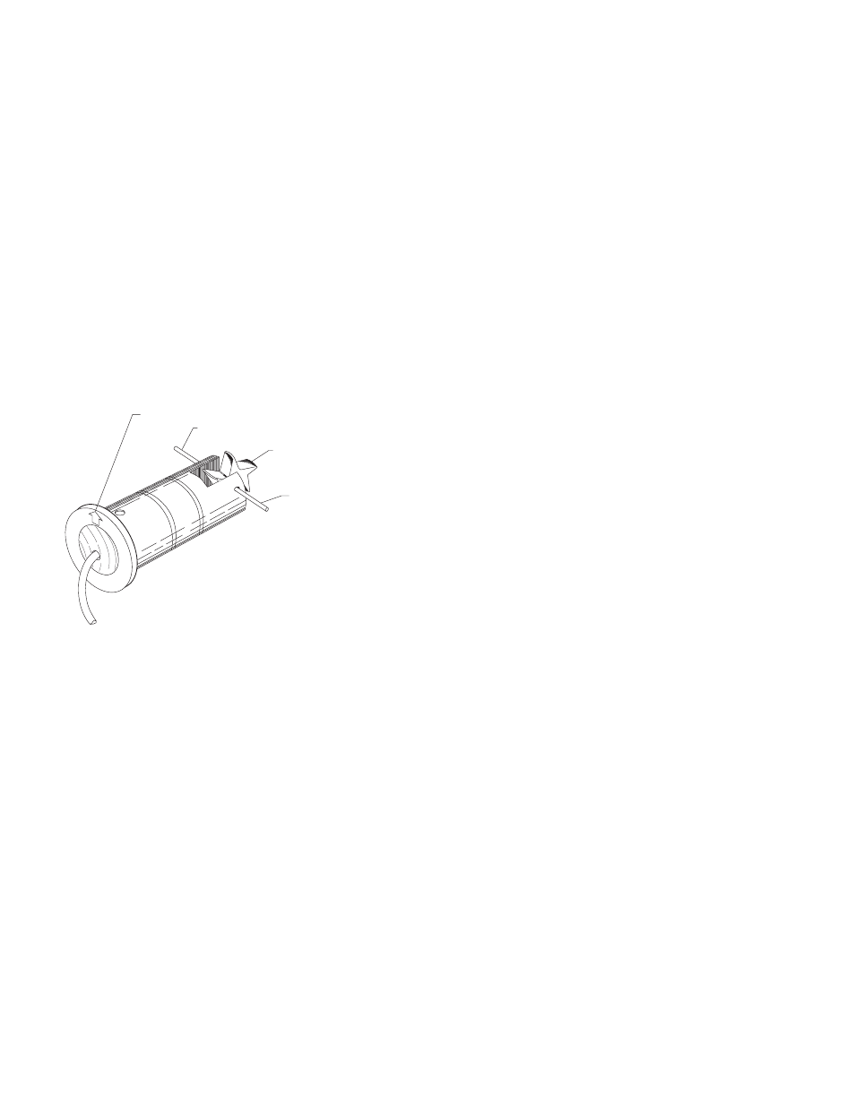
NOTE DIRECTION OF ARROW
USE PLIERS HERE
NOTE DIRECTION OF
IMPELLER
USE METAL PIN TO
REMOVE CERAMIC SHAFT
Figure 4
Impeller Assembly and Shaft Replacement
3) Remove the sensor from the hex adapter or the tee.
4) Note the impeller blade orientation relative to flow arrows
and the alignment hole in metal sensors beside one of
the sighting holes. In order to maintain proper calibra-
tion, the impeller will have to be reinstalled in the same
manner with the impeller blades pointing toward the
small alignment hole, and into the flow direction as indi-
cated by the flow arrows.
5) To remove the old impeller blade assembly, push the
old shaft out of the sleeve with the new shaft (or small
diameter rod) just far enough to grab the end with a pair
of pliers and pull the shaft completely out. The impeller
assembly will now be free and will drop out.
6) Inspect the shaft and bearings for wear, and replace as
necessary.
7) Refer to figure 4. To reinstall, position the impeller in the
cavity oriented as in step 4 so that the impeller blades
point into the flow direction and toward the small align-
ment hole located beside one of the sighting holes on
metal sensors.
8) Carefully push the shaft through the sleeve and impel-
ler taking care not to damage the bearings. Make sure
that the shaft is inserted far enough so that it clears the
sleeve on each side of the impeller housing.
NOTE: If shaft is not carefully installed, the bearing can be
deformed preventing free rotation.
9) Inspect the O-rings for damage and replace as neces-
sary. Clean the O-rings and the sleeve and relubricate
with silicone grease from the packet provided or some
other acceptable lubricant.
10) Install the sensor into the 2 inch NPT adapter or tee so
that alignment hole is facing upstream and flow arrows
point in the direction of the actual flow. Since the po-
sitioning collar was not loosened during this operation,
the studs should all line up perfectly when the sighting
holes are parallel to pipe. If this has been accidentally
loosened, please refer to the installation instructions for
the alignment of the flow sensor unit.
11) Install and tighten the nuts.
12) For metal sensors, double check that the distance from
the top of the 2 inch NPT adapter to the bottom of the
positioning collar equals the dimension as measured in
step 2, and holes in sleeve sight exactly down the pipe,
the arrows point in direction of flow and alignment holes
located beside one sighting hole is pointing towards the
source. If not, refer to installation section in this manual.
13) This completes the replacement procedure. The system
may now be repressurized and tested.
TROUBLESHOOTING
1)
If the voltage at the sensor input is less than 7 VDC
in a no flow situation, disconnect the sensor from the
barrier strip and measure the voltage at the sensor
input terminals of the barrier strip again. It should be
between 8 VDC and 20 VDC. If the voltage at the sen-
sor input is still below 7 VDC or 3 VDC, the problem
may be with the monitor (hardware or programming).
2)
If you suspect that the sensor is bad, you can test the
monitor circuitry by connecting a piece of wire to one
of the sensor input terminals and tap the other side
of the wire to the other sensor input terminal. Short-
ing across the sensor input terminals ON and OFF
repeatedly allows the display to respond by trying to
calculate a flow rate for the frequency of your short-
ing action. If the display does not show a change from
0.00, it indicates a problem with the monitor.
3)
If the monitor tests ok and there are any splices in the
cable, break the sensor cable at the splice closest to
the sensor and retry the shorting test in step 2.
4)
If the cable tests ok, drain the pipe line, verify the
pressure is off, remove top lock nuts holding the sen-
sor electronics. Spin the impeller by hand. If flows are
noted on the display, and impeller spins freely then
the flow rates may have been below our design mini-
mums or the line was full of air. Try again. If the sensor
fails to respond then replace sensor.